N7201A616E00_0317.pdf - 第333页
NPM-W 2 EJM7DE-MB-05O-0 0 5-3-2 -4 Solder inspection
NPM-W2 EJM7DE-MB-05O-00
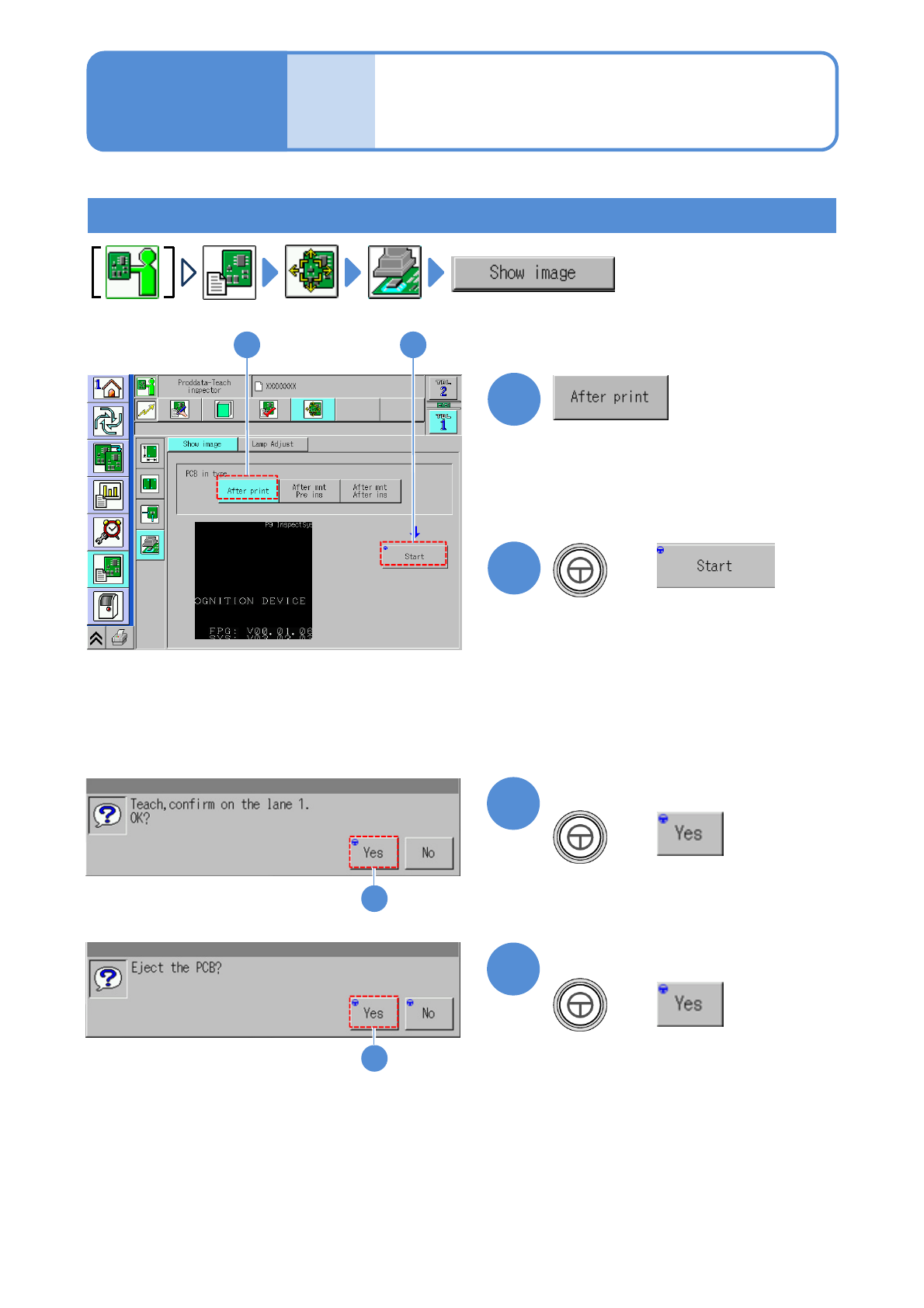
Capturing the images of teaching PCB
1
2
+
3
Confirm the message
4
Confirm the message
3
+
+
Capturing the images
of teaching PCB 2
Operating procedure
5-3-2
Produc-
tion data
and
teach
●PCB after print means the condition
that no component is placed on the
PCB.
Uses to set the PCB color.
5-3-2-3
Loads a PCB and starts taking the image
of the entire PCB. The captured image
will be stored in the inspection BOX.)
●PCB is unloaded after the mage is
taken.
●A message appears when there are
not any PCBs in the upstream
machine.
1 2
4

NPM-W2 EJM7DE-MB-05O-00
5-3-2-4
Solder
inspection
NPM-W2 EJM7DE-MB-05O-00
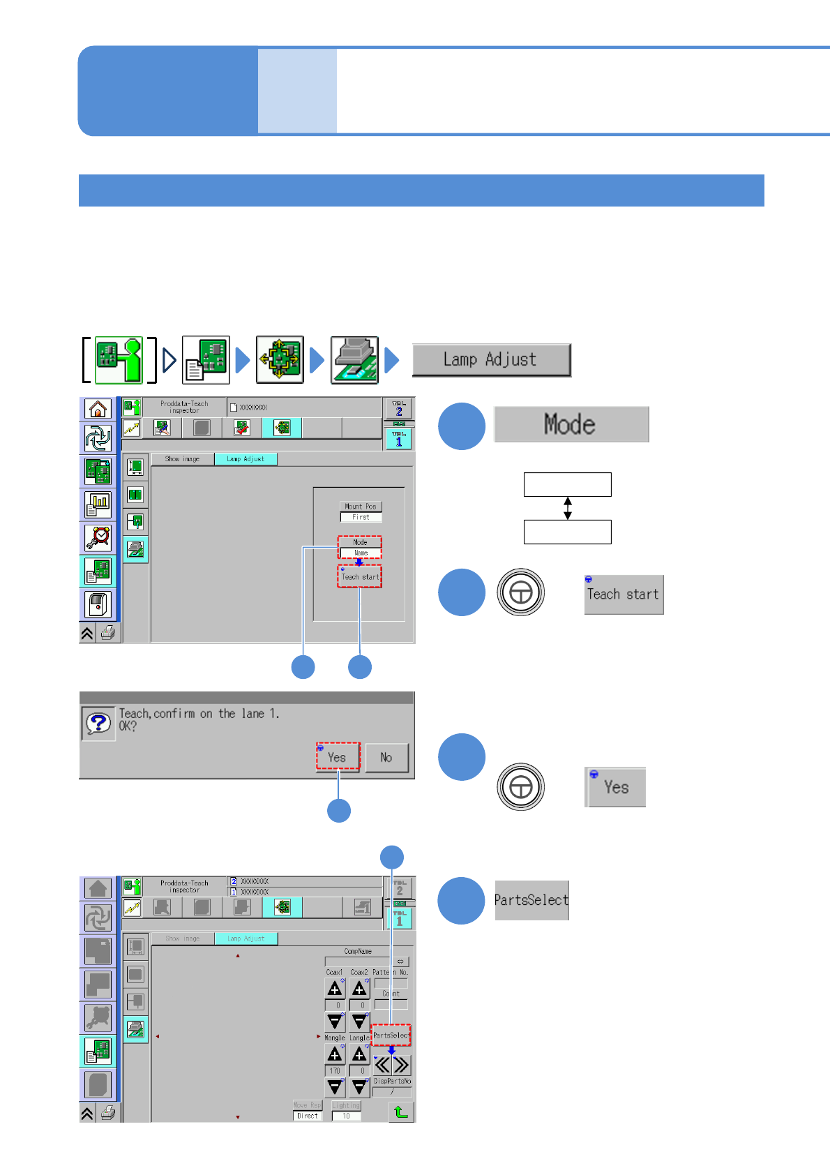
Checking the lighting condition (Unnecessary under normal condition)
Operating procedure
5-3-2
1
Name
Comment
●Choose the component search mode.
2
+
1
■When the mode is a component name
1
Produc-
tion data
and
teach
Capturing the images
of teaching PCB 3
1 2
3
3
Confirm the message
The lighting adjustment function is used only if difficult to inspect solders in the normal lighting conditions.
Move the inspection head to a solder location, and, checking the image, adjust the lighting to the condition
(high contrast condition) best suited for inspection. For your information, if applying the adjusted lighting
condition for the inspection condition, set the lighting condition in 2D inspection editor on a per-solder basis.
(→[NPM-DGS 2D inspection editor])
●Even though the PCB after solder printing is used, the head is moved to the placement position to specify
the component.
5-3-2-5
(PCB is loaded, and the component
search/image confirmation screen is
displayed)
●A message appears when there are
not any PCBs in the upstream machine.
+