N7201A616E00_0317.pdf - 第356页
NPM-W 2 EJM7DE-MB-05O-0 0 Defec- tive PCB process 5-5-2 -1 Pr ocessing method Operating procedure 5-5-2 The processing method differs depen ding on the condition s and judgment result of solder inspection. ( → Chapter 7 …
NPM-W2 EJM7DE-MB-05O-00
Depending on solder inspection conditions and the presence/absence of a defective PCB being at rest on the
ejection conveyor, the processing method differs. Use solder inspection condition suitable for your production
pattern. (→P.5-5-2)
Solder inspection condition
Whether defective PCB
stops or not
1)
Processing method
Placement after all solders
inspection
Stops
●When skipping placement on PCB
3)
After removing an unplaced PCB,
dispose of it, or clean it for reuse.
●When selecting “NG placement”
Check or repair the defective part of
a component or solder.
Placement by pattern after all
solders inspection
No stopping
2)
●When skipping placement in a
pattern
3)
Dispose of a defective pattern with no
components placed.
●When selecting “NG placement”
Check or repair the defective part of a
component or solder.
Solder inspection right before
placement
Stops
●When skipping placement on PCB
4)
Check or repair the defective part of a
component or solder.
●When selecting “NG placement”
Check or repair the defective part of a
component or solder.
■Defective PCB processing
1) Since PCB cannot be repaired or removed before reflow without setting up an ejection conveyor, it is
recommended to use [Placement after all solder inspection] or [Placement by pattern after all solders
inspection] as the solder inspection condition.
2) When NG placement is selected for the defective part of solder during the over judge input, the ejection
conveyor stops for verification of PCB.
3) When component inspection comes after solder inspection, the component inspection will not be
conducted on the skipped pattern.
4) When component inspection comes after solder inspection, the component inspection will not be
conducted on the skipped PCB. Component inspection, however, will be conducted on the PCB flowing
into the process downstream from the ejection conveyor since it is considered as a repaired PCB.
5-5-1-2
Solder
inspection
NPM-W2 EJM7DE-MB-05O-00
Defec-
tive PCB
process
5-5-2-1
Processing method
Operating procedure
5-5-2
The processing method differs depending on the conditions and judgment result of solder inspection.
(→ Chapter 7 in [NPM-DGS] operating instruction)
●The judgment result is determined by the over judge input of solder inspection result. (→P.5-4-3)
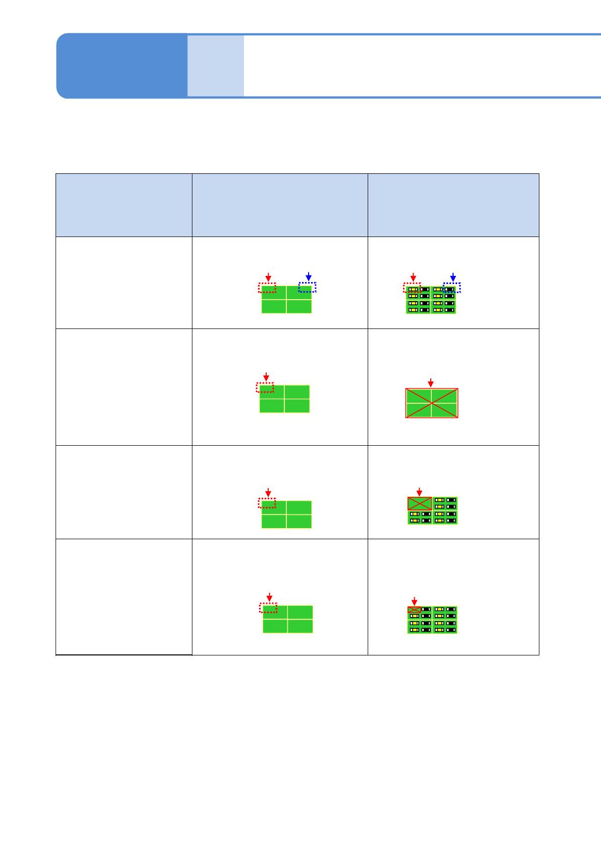
Solder inspection condition Judgment result Processing method
Common to all conditions
For “OK” or “NG placement”
・Places components.
Placement after all solders
inspection
(After all solders are
inspected, placement only
for solder conforming
PCBs)
In the presence of more than one
“NG” solder on a PCB
・Skips placement on PCB.
Placement by pattern after
all solders inspection
(After all solders are
inspected, placement only
for solder conforming
patterns)
In the presence of more than one
“NG” solder in a pattern
・Skips placement in a “NG”
pattern.
Solder inspection right
before placement
(Inspection and placement
are alternatively carried
out and only conforming
components will be
placed)
In the presence of more than one
“NG” solder on a per-component
basis
・Skips placement of a component
corresponding to the “NG”
solder.
NG
placement
OK
NG
placement
OK
NG
NG
NG
Skip
Skip
Skip
NPM-W2 EJM7DE-MB-05O-00
5-5-2-2
■Reminder for setting
There are following restrictions on condition settings. Please note that If you set against the conditions, we
cannot assure the operating performance of the machine.
1. About NG ejection (For [Solder inspection right before placement])
When solder inspection results in NG and when a component to be placed by the diagonal head is
skipped, the component will be ejected as NG provided that it is already picked up.
Ejected components can be reused by the use of the NG ejection conveyor or trays. If, however, you
want to control an ejection itself, set the following data on a per-part basis with DGS. By doing so, a
component will not be picked up before the inspection result is defined so that you can avoid using NG
ejection. Note that it is in exchange for slower production tact time.
Placement condition data: Proceeded pickup before inspection (not turned) OFF
●Default is (turned) ON
2. About PCB removal
When component are being placed, it is not possible to reload defective PCBs removed from the
ejection conveyor into the inspection head-equipped machine after repair (possible if it is before
component placement)
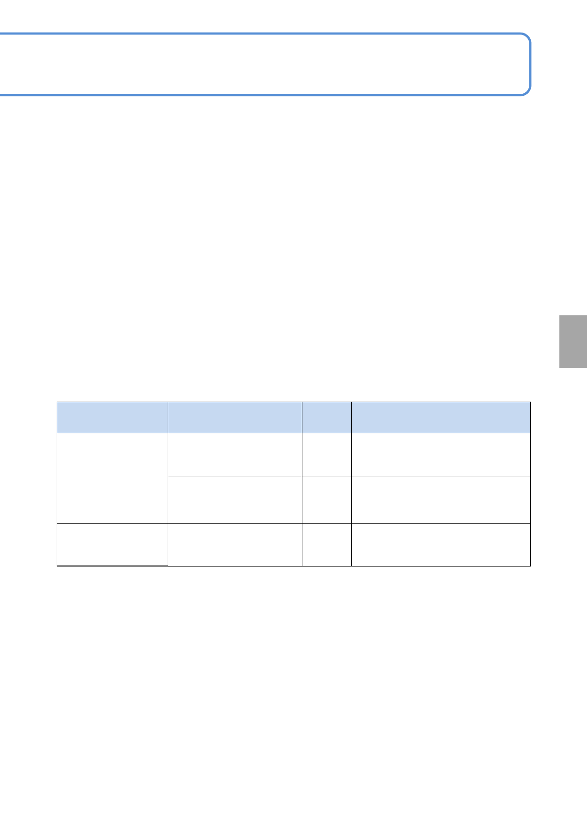
Major item Item Setting Remarks
Data creation job
editor
→
Communication
setting
(Communication
switch)
Receiving inspection
information (APC)
ON First machine: OFF
Middle machine: ON
Last machine: ON
Sending inspection
information (APC)
ON First machine: OFF
Middle machine: ON
Last machine: ON
2D inspection editor
→
PCB detailed setting
Skip control ON Control of placement skip
■DGS setting (production data)
To reflect solder inspection results and placement processes in several machines, you need to define the
following conditions on NPM-DGS.
(→Chapter 7 in [NPM-DGS] operating instruction and Chapter 4 in [NPM-DGS 2D inspection editor])
Solder
inspection