N7201A616E00_0317.pdf - 第652页
NPM-W 2 EJM7DJ-MB-08O-00 System function details Operating procedure 8-2-2 8-2-2 -3 V arious settings 2 ■ Setting items by a PCB ● Ethernet conducts the communication betw een machines. ● The production data setting of t…
NPM-W2 EJM7DJ-MB-08O-00
■Setting items by a component
Setting item Description
APC control switch
Placement control
X direction correction
Y direction correction
Angle correction
Choose whether control (correction) is carried out for each direction or
not.
ON :Controlled (Corrected)
OFF : Not controlled (not collected)
Ratio of correction amount
Electrode direction
Non-electrode direction
Angle direction
Set the ratio of the correction value for each direction. 0-100 [%]
●The correction value is limited by the value multiplied this ratio to
the measurement result.
Threshold of correction value
Electrode direction
Non-electrode direction
Angle direction
Set the threshold of the correction value for each direction. [mm]
●If the measurement result exceeds this value, the correction value
is limited to this value.
Feed-forward offset
X-direction
Y-direction
Set the offset for feed forward.
●Place the component to the position where this value is added to
the solder position of the measurement result.
Measurement control Non-target: It is not target for measurement control.
Target: It is target for measurement control.
●If the measurement mode is [By pattern] or [By pattern (correction
at 2 points)], [Target] of the component for one or two point s must
be set per pattern.
Individual correction No: Individual correction does not carried out
Yes: Individual correction is carried out
●If the measurement mode is By pattern] or [By pattern (Correction
at 2 points)], the self solder position measurement result is applied
to the correction value for the specified component.
Placement standard Solder: Measure by solder placement basis.
Land: Measure by land placement basis.
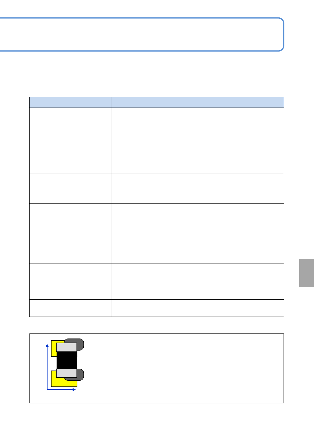
Electrode direction:
Placed to a position completely (100%) responded to the position where a
solder joint is misaligned
Non-electrode direction :
Placed to a position half (50%) responded to the position where a solder
joint is misaligned
●A component with electrodes on both sides such as a minitrans or SOP are
applicable. (QFP and BGA are inapplicable)
*1)Example when the ratio of the correction value for non-electrode direction is set to 50%
*1)
8-2-2-2
50%
100%
Non-electrode
direction
Electrode
direction
APC
system
NPM-W2 EJM7DJ-MB-08O-00
System
function
details
Operating procedure
8-2-2
8-2-2-3
Various settings 2
■Setting items by a PCB
●Ethernet conducts the communication between machines.
●The production data setting of the printing machine is also required. For details, see the operating manual
[NPM-DGS SP data editor].
●When the machine manufactured by other companies is used, see the operating instruction [Other
machine’s Inspection machine interface software].
Setting item Description
Printing control Choose [ON] to control the printing position with APC.
Feedback function

NPM-W2 EJM7DJ-MB-08O-00
8-2-2-4
APC
system