N7201A616E00_0317.pdf - 第376页
NPM-W 2 EJM7DE-MB-06O-0 0 6-1-8 -3 5 4 4 ● Choose the placeme nt position offset data to display the related data. ● Choose the trend rang e check data to display the related data. ● Choose the center rang e check data t…
NPM-W2 EJM7DE-MB-06O-00
6-1-8-2
A
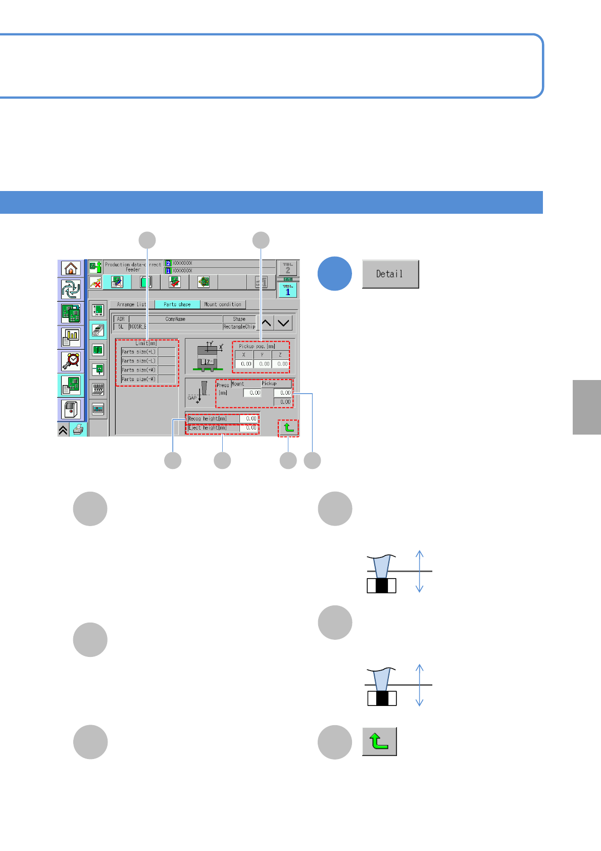
Limit
Recog height
Pickup pos.
B
D
C
E
Press
+
-
+
-
●+ L: Tolerance of a component length
in + direction.
●- L: Tolerance of a component length in
- direction.
●+ W: Tolerance of a component width
in + direction.
●- W: Tolerance of a component width in
- direction.
2
F
Returns to the previous screen.
Enter the recognition height.
Eject height
Enter the eject height.
Confirm and edit the detailed data.
Setting
change
A
CD E
B
F
●Mount:
The placement gap [mm]
●Pickup:
The pickup gap [mm]
(*Editable only for 2- and 3-nozzles)
NPM-W2 EJM7DE-MB-06O-00
6-1-8-3
54
4
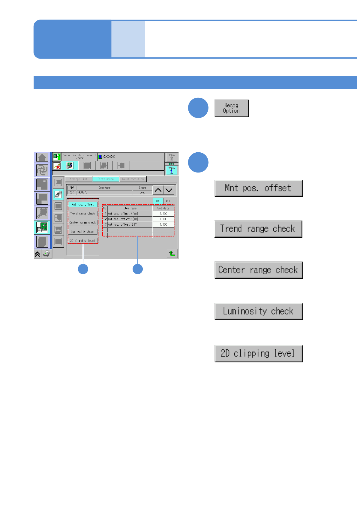
●Choose the placement position
offset data to display the related
data.
●Choose the trend range check data
to display the related data.
●Choose the center range check
data to display the related data.
●Choose the luminosity check data
to display the related data.
●Choose the 2D clipping level data
to display the related data.
Choose the desired item to
confirm
Data
editing
Component shape data
edit 2
Square chip component 2
Operating procedure
6-1-8
3
Confirm and edit the recognition option
data.
NPM-W2 EJM7DE-MB-06O-00
6-1-8-4
5
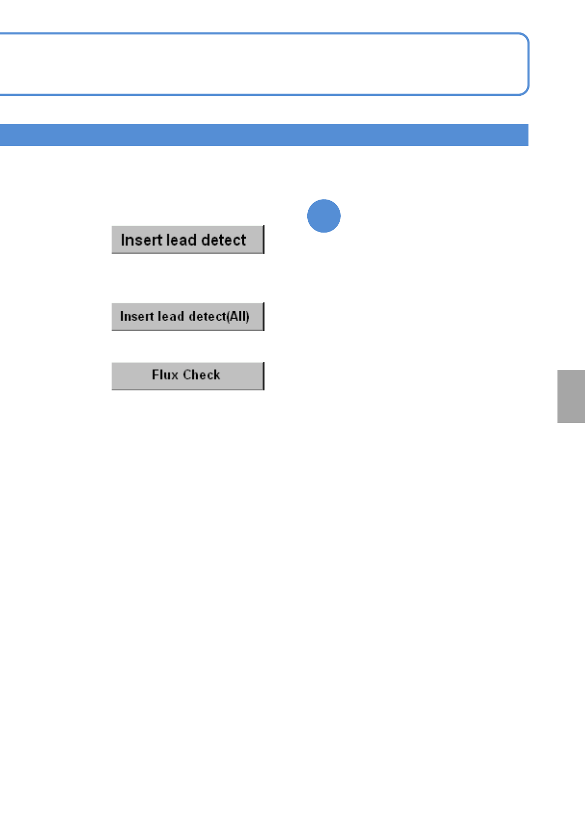
Edit the desired item
●Choose the insertion lead detection
to display the related data.
●Choose the insertion lead (all) to
display the related data.
●Choose the flux check data to
display the related data.
Setting
change