YSM10安装调整(eng).pdf - 第39页
For Ser v ice E n gineer Service Information SI1610004E -000= YSM10_Proced ures for the adjustmen ts required after installing a machine 39/107 5. “ A CP- Chip ” P PQ Q Q @ @ H H H Q QR R R I I Q QP P PP P P @ @ Q …
For Service Engineer
Service Information
SI1610004E-000= YSM10_Procedures for the adjustments required after installing a machine
38/107
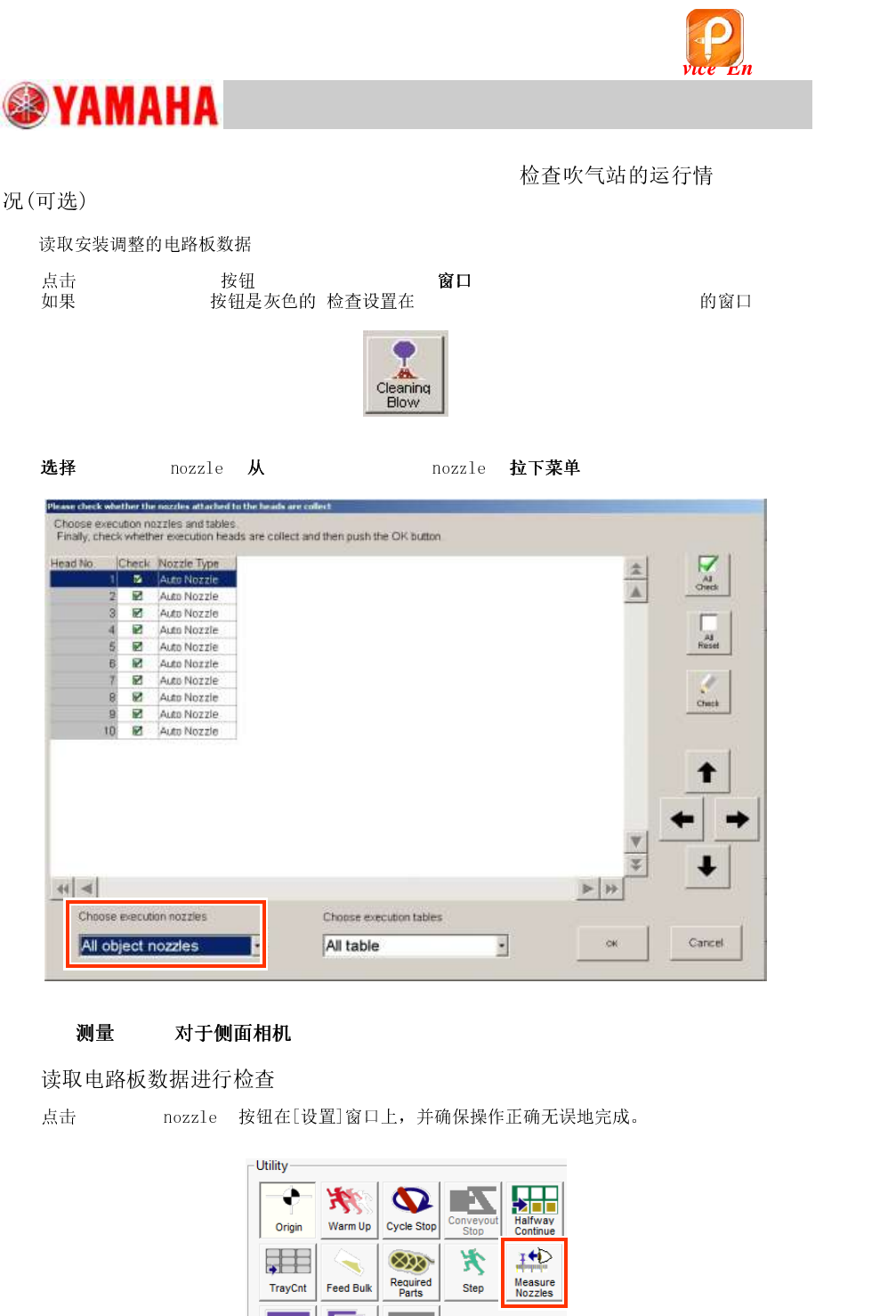
4.14 Check the operation of the blow station (Option)
1. (ANC_TEST_YSM10_* or ACP_1005_*HEAD_*).
2.
[Cleaning Blow] on the [Unit] - [Head] .
[Cleaning Blow] , “Schedule Specification” VmSpec.
Figure 47
3.
“All object s” “Choose execution s” .
Figure 48
4.15 “
”
1. (ANC_TEST_YSM10_*).
2.
[Measure s]
Figure 49
该文档是极速PDF编辑器生成,
如果想去掉该提示,请访问并下载:
http://www.jisupdfeditor.com/
For Service Engineer
Service Information
SI1610004E-000= YSM10_Procedures for the adjustments required after installing a machine
39/107
5. “ACP-Chip”
PPQQQ @@HHH QQRRR II QQPPPPPP @@ QQPPP
HH II @@
:
[ ]
Camera Number
Type
Camera location
Max XY (mm)
Max Z (mm)
Digital Camera 1
Move C
Right side of the head
8 sq.
0
Digital Camera 2
Move C
Left side of the head
8 sq.
0
Digital Camera 3
Scan B Main
All-in-one
12 sq.
7
Digital Camera 4
Scan B Side
4 sq.
1.2
Digital Camera 5
Digital Multi C
Qty:1
On the front or rear side
(
*1)
45 sq. (55)
15
Digital Camera 6
Digital Multi C
Rear side
45 sq. (55)
15
Table 23
(
*1):
If the machine is equipped with two (2) Multi cameras Front: “Digital 5 / Rear: Digital 6
If the machine is equipped with only one (1) Multi camera
Wherever the camera is mounted (Front or Rear), the camera is “Digital 5”.
5.1 Requirements for the adjustment
Required boards and components
Item
Part Name
Part No.
Qty
ACP board
PCB
ASSY.4
KM0-M8810-40
1
(Select
either of the
boards)
20 mm width
double-sided tape
AMF board
PCB
ASSY.1
KM0-M8810-10
35 mm width
double-sided tape
1005 Ceramic chip
components (Reel)
REEL CERAMIC
1005
KGA-M880C-10
Components used
for the mounting
adjustment.
Table 24
该文档是极速PDF编辑器生成,
如果想去掉该提示,请访问并下载:
http://www.jisupdfeditor.com/

For Service Engineer
Service Information
SI1610004E-000= YSM10_Procedures for the adjustments required after installing a machine
40/107
5.2 Check the option setting
A new item “Timer Setting” has been added next to the “Timer (minute)” item on the “Multi MACS”
and the “BaseMACS” windows (See “Setting”
“Machine Data”
“Precision”
“MultiMACS/
Base MACS” on the VmSpec window).
Make sure that “Timer Setting” is set to “Auto”.
:
By setting the “Timer Setting” item to “Auto”, the recognition distance is automatically adjusted
according to the variation of the thermal expansion of the X and the Y axes.
If it is set to “Manual”, the recognition is performed by the distance set in the “Timer (minute)” field.
Multi MACS – “Timer Setting” (For Multi Camera)
Figure 50
[When “Timer Setting” is set to “Manual”]
Select “Machine Data”
”Precision”
“Multi MACS” from the tree view on the left side of the
VmSpec window, and make sure that “Timer (minute)” is set to “1”.
If the value is too large, it affects the mounting accuracy, and if it is too small, it affects the tact
time.
Figure 51
:
If the “Multi MACS” checkbox on the [Parts] – [Vision] window (Part Information - Ceramic 1005) is
ticked, the Multi MACS is recognized every time during the ACP-Chip adjustment process.
Multi MACS – “Timer Setting” (For Scan Camera)
Select “Machine Data”
”Precision”
“Multi MACS” from the tree view on the left side of the
VmSpec window, and make sure that “Timer (minute)” is set to “1”.
If the value is too large, it affects the mounting accuracy.
Figure 52
:
If the “Multi MACS” checkbox on the [Parts] – [Vision] window (Part Information - Ceramic 1005) is
ticked, the Multi MACS is recognized every time in the ACP-Chip adjustment.
该文档是极速PDF编辑器生成,
如果想去掉该提示,请访问并下载:
http://www.jisupdfeditor.com/