YSM10安装调整(eng).pdf - 第88页
For Ser v ice E n gineer Service Information SI1610004E -000= YSM10_Proced ures for the adjustmen ts required after installing a machine 88/107 1 1.3 A dj ustment s r elated to the mounting accuracy W hen pe rform ing th…

For Service Engineer
Service Information
SI1610004E-000= YSM10_Procedures for the adjustments required after installing a machine
87/107
11.2 Workflow for when “AMF Index 1“ falls below 1.000
After checking the VgChart and finding the problem, identify the cause of the problem and take
appropriate measures. And then perform the ACP-Chip adjustment again.
If the cause of the problem cannot be identified, perform the adjustment of all the items in “11.3
Adjustments related to the mounting accuracy” a g a i n .
After readjusting the basic adjustments, perform the ACP-Chip adjustment again.
1. Identify the cause of the problem on the VgChart.
Check the tendency of the deviation of the mounting positions on the VgChart.
・ Does the deviation occur repeatedly?
・ Does the deviation occur to all the heads in the same way?
2. Check the following possible causes of the problems assumed by the mounting result on
the VgChart.
・ Is the machine installed properly?
・ Is the board clamped properly?
・ Is the attached to the head properly?
・ Are the components and the mark recognized properly?
・ Any abnormality found in the recognition unit?
(Is the camera installed properly? Are the lenses clean?)
・ Others
3. Readjust the basic data.
If the cause of the problem can be identified, readjust the related basic data.
See “11.3 Adjustments related to the mounting accuracy” for the adjustment items.
When any error occurs in the ACP-Chip adjustment by the main camera
Perform the adjustment for all the cameras.
When any error occurs in the ACP-Chip adjustment by the sub camera
Perform the adjustment only for the sub camera.
When any error occurs in the ACP-Station adjustment by the sub camera.
Feedback the correction values instead of readjusting the basic data.
4. Check the mounting accuracy after feeding back the correction values.
After saving the correction values in the machine data, perform the ACP-Chip accuracy check
again.
该文档是极速PDF编辑器生成,
如果想去掉该提示,请访问并下载:
http://www.jisupdfeditor.com/
For Service Engineer
Service Information
SI1610004E-000= YSM10_Procedures for the adjustments required after installing a machine
88/107
11.3 Adjustments related to the mounting accuracy
When performing the basic adjustments for the machine, read the board data for adjustment
“MCH_SETUP” beforehand.
11.3.1 Fiducial camera - “” adjustment
Perform the “” adjustment by recognizing the
0.5mm mark on the board.
1. Set the board for the adjustment on the conveyor.
2. Trace the “Board offset” position (
0.5mm mark on the board).
Caution:
If the machine is equipped with the optional sub camera, the camera closer to the mark is automatically
selected. Check the camera that has moved to the mark position.
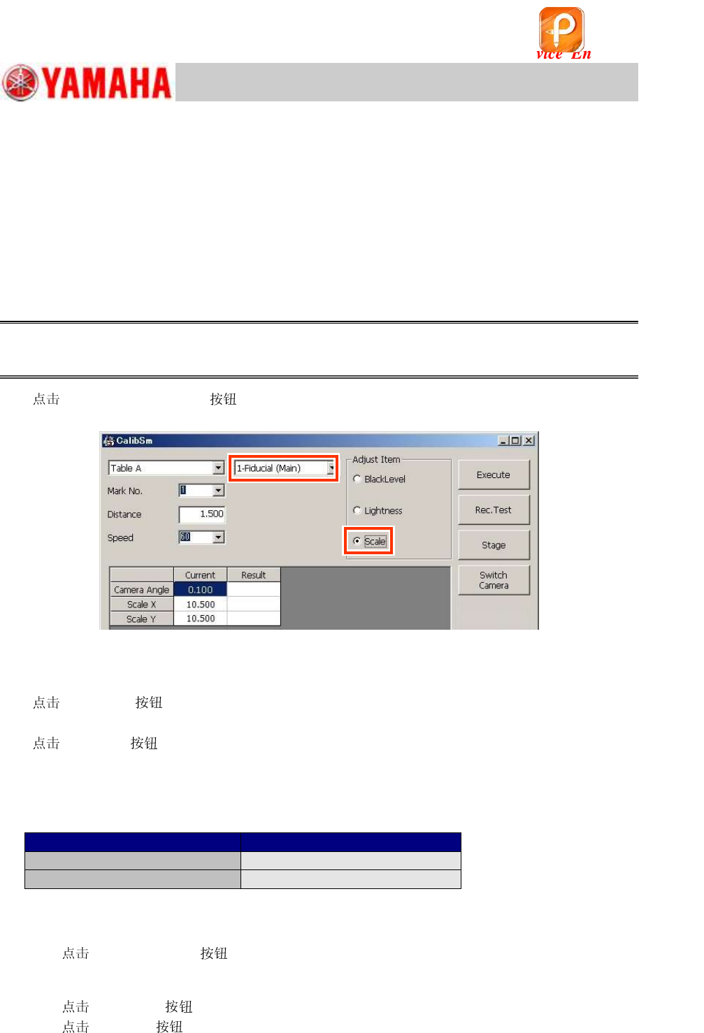
3.
[007 Fiducial camera] on the CalibSm main menu, and select “” from
“Adjust Item”.
Figure 130
4. Select the camera.
Select the camera that has moved to above the
0.5mm mark (“Board offset” position).
5.
[Rec Test] .
After the mark is recognized, the camera moves to the center of the mark.
6.
[Execute] .
The camera moves 1.5mm to the X and to the Y directions, and the and the camera angle
are measured.
7. Check the measurement results and save the data.
Make sure that the values meet the specification and save them.
Item
Specified value
Fiducial Camera X, Y
10.280 ~ 10.880
m
Camera Angle
0.000 +/- 0.500 degrees
Table 39
8. If the machine is equipped with the optional sub camera, perform the adjustment for both
the cameras.
1) [Switch Camera] .
The other camera moves to above the
0.5mm mark and the setting of the Camera type is
switched automatically.
2)
[Rec. Test] .
3)
[Execute] .
4) Check the measurement results and save the data.
该文档是极速PDF编辑器生成,
如果想去掉该提示,请访问并下载:
http://www.jisupdfeditor.com/
For Service Engineer
Service Information
SI1610004E-000= YSM10_Procedures for the adjustments required after installing a machine
89/107
11.3.2 Fiducial camera – “Lightness” adjustment
If the machine is equipped with two fiducial cameras (Option), perform the adjustment for both the
cameras.
The “Black level” adjustment does not need to be performed. (It is required when the camera is
replaced.)
The “Target” value of the “Lightness” adjustment varies depending on the light adjuster type and
the LED version of the lights.
Select the light adjuster before performing the adjustment.
When the LED version has been changed (the part of the LED has been changed), change
the version of the LED beforehand.
:
See Service Information “SI1107002E=YS24 Series_CalibSm Adjustment Manual - 24.2. How to
change the settings of the LED version” for how to change the LED version.
:
See “2.1 Jigs for the “Lightness” adjustment of the cameras” for the types of the light adjusters.
1. Set the light adjuster.
1) Raise the pushup plate.
[Push Up] on the [Unit] – [Conveyor] window in order to raise the pushup plate.
Enter “4.0mm” in the “Thickness” field.
2) Set the pushup pins.
Set three (3) pushup pins so that the light adjuster can be placed on
them.
3) Place the light adjuster on the pushup pins with its gray surface
facing up.
If the adjuster is not level, check if the height of the pushup pins is
even.
Figure 131
2. Perform teaching for the light gray part of the light adjuster.
[Unit] and then the [Axis] . Move the head so that the light gray part of the
adjuster fills the window of the fiducial camera 1 (the camera on the right).
* If the Scan camera is under the fiducial camera, move it from under the fiducial camera.
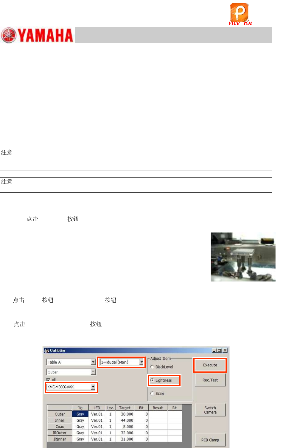
3.
[007 Fiducial Camera] on the CalibSm main menu.
Select “Lightness” from “Adjust Item”, and make sure that “1-Fiducial (Main)” is selected from the
pull-down menu at the upper part of the window.
Figure 132
Step 3
Step 3
Step 4
Step 5
该文档是极速PDF编辑器生成,
如果想去掉该提示,请访问并下载:
http://www.jisupdfeditor.com/