YSM10安装调整(eng).pdf - 第55页
For Ser v ice E n gineer Service Information SI1610004E -000= YSM10_Proced ures for the adjustmen ts required after installing a machine 55/107 6. “ A CP-St ation ” adjustment (with a QFP and the Multi camera) After…

For Service Engineer
Service Information
SI1610004E-000= YSM10_Procedures for the adjustments required after installing a machine
54/107
C. If the variation and abrupt shift are found in the mounting result
If the mounting state is unstable, accurate measurement data cannot be obtained. Therefore, the
mounting result cannot be improved no matter how many times the feedback is performed.
Identify the cause of the problem and take appropriate measures.
[Items to be checked]
Is the board clamped properly?
Does the component reach the board surface properly when it is being mounted?
Is the mark recognition performed in the stable condition?
(The mark should be clean and the mark information should be correct.)
Is the component supply unit feeding the component properly, and the components are
picked up properly?
Are the components recognized properly?
Is the clean or secured properly?
Are the lens of the camera and the lighting part clean?
Is the camera mounted to the machine properly?
If any problems are detected, take appropriate measures and perform the ACP-Chip adjustment
again.
When performing the adjustment of the board edge clamp unit, the data of the following items
may need to be adjusted.
[Items to be adjusted]
“PCB Height”
“Head Offset Z”
Caution:
The “” adjustment for the fiducial camera needs to be performed only when the AMF Index 1 falls
below 1.000 with the main camera (for recognizing components).
If the AMF Index 1 falls below 1.000 when checking the mounting accuracy with the sub camera, the
adjustment is not required.
该文档是极速PDF编辑器生成,
如果想去掉该提示,请访问并下载:
http://www.jisupdfeditor.com/

For Service Engineer
Service Information
SI1610004E-000= YSM10_Procedures for the adjustments required after installing a machine
55/107
6. “ACP-Station” adjustment (with a QFP and the Multi camera)
After completing the “ACP-Chip” adjustment by using the Multi camera and 1005 ceramic chip
components, perform the accuracy adjustment for each with the “ACP-Station” utility by
mounting a QFP on the FAMF station.
304A(315A) 68-pin QFP
307A(318A) 208-pin QFP
:
When the machine is equipped with the Multi camera, 304A(315A) s and 307A(318A) s,
perform the ACP-Station adjustment.
Also, when the customer has the required s and the head that the is to be attached is
determined, perform the adjustment.
6.1 General description of the “ACP-Station” adjustment
No special board data is required for the adjustment as “MCH_SETUP.ygx.” is used as the board
data.
The “ACP-Station” utility provides the following features:
All the heads, cameras and s can be adjusted consecutively
In the “ACP-Station” utility, you can perform the adjustment for all the heads, cameras and s
consecutively once you complete the initial setting.
Automatic feedback
In the “ACP-Station” utility, the mounting accuracy is judged automatically to determine whether to
perform feedback or not.
Minimum amount of components are required for the adjustment
The minimum amount of components necessary for the adjustment is statistically calculated, which
enables the adjustment to be performed with fewer components and reduces the time for the
adjustment process.
The function that copies the accuracy parameters
The adjustment results of the main camera are reflected to the other cameras automatically, which
reduces the time to adjust the other cameras.
该文档是极速PDF编辑器生成,
如果想去掉该提示,请访问并下载:
http://www.jisupdfeditor.com/
For Service Engineer
Service Information
SI1610004E-000= YSM10_Procedures for the adjustments required after installing a machine
56/107
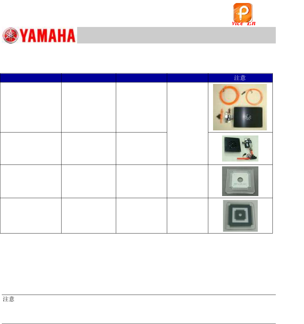
6.2 Required jigs
Table 28
Board data
Read the board data (MCH_SETUP.ygx) and check the version of the data in the “Board
Comment” field on the [Board]–[Board] window.
Required version: Ver.1.058 or later
:
Make sure to read the board data before the adjustment as the “Mark Information”, “Part Information”
and the “Board Information (Board size X, Y and Z) of the board data “MCH_SETUP” will be used for
the ACP-Station adjustment.
Item
Part Name
Part No.
Qty
FAMF Station
(Plate size: 240x170)
FAMF STATION
ASSY.
KGA-M88F0-A0
1
(Use either of
the stations.)
Small FAMF Station
(Plate size: 100x100)
FAMF STATION
S.ASSY.
KGA-M88F0-B0
68-pin QFP
QFP 68P
KW8-M880A-10
1
208-pin QFP
(With the sticker)
QFP 2S
KM0-M880A-20
1
该文档是极速PDF编辑器生成,
如果想去掉该提示,请访问并下载:
http://www.jisupdfeditor.com/