YSM10安装调整(eng).pdf - 第66页
For Ser v ice E n gineer Service Information SI1610004E -000= YSM10_Proced ures for the adjustmen ts required after installing a machine 66/107 4. Check the setting of “M ar k” . Select the m ark number to be used when p…
For Service Engineer
Service Information
SI1610004E-000= YSM10_Procedures for the adjustments required after installing a machine
65/107
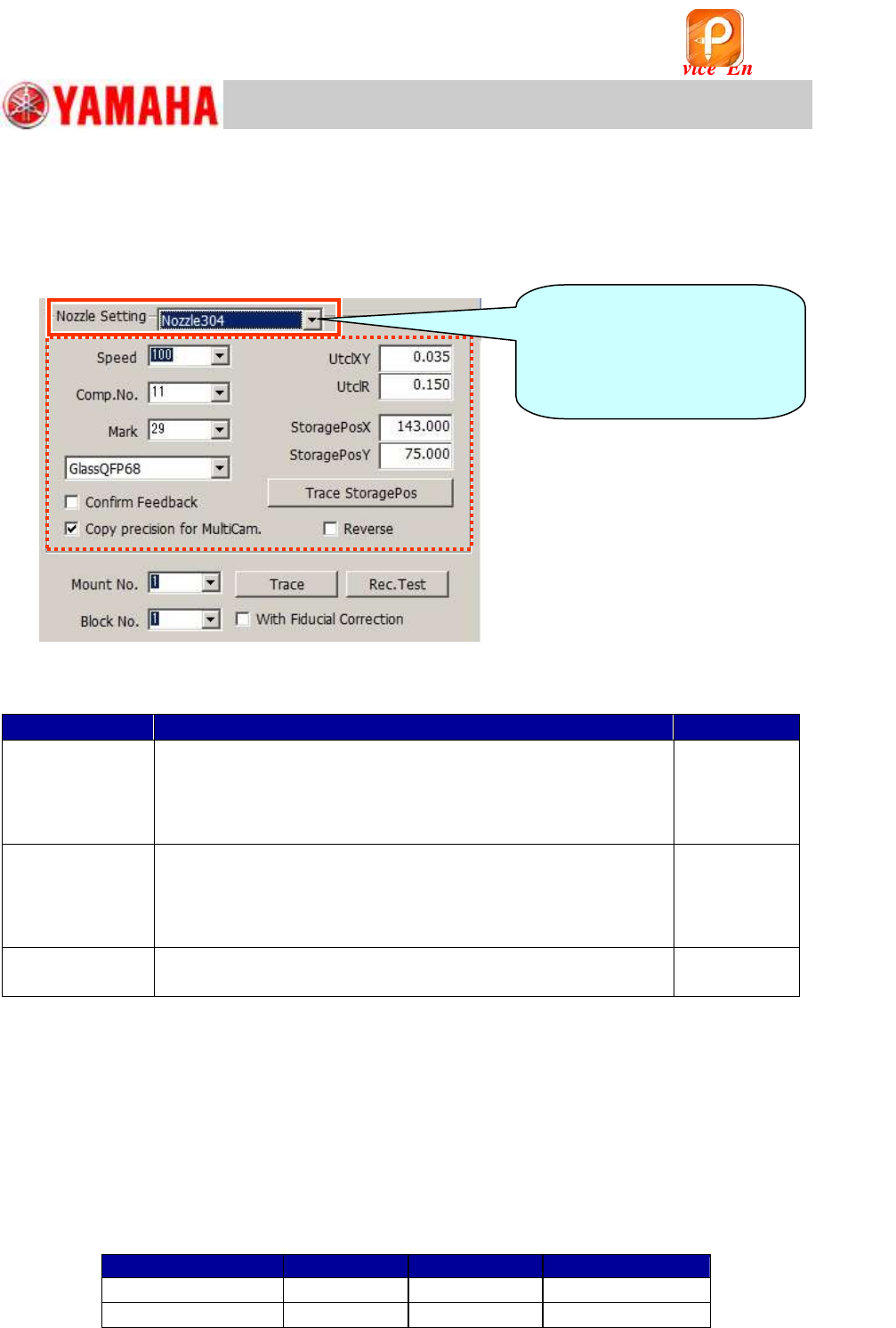
6.7.2 Setting for the items on the right side of the “AutoRun/Measure” window
On the right side of the “AutoRun/Measure” window, you can perform setting for each and
specify the “Mount No.” and the “Block No.”.
The s that can be adjusted with the machine are displayed in the “ Setting” pull-down
menu.
Figure 88
Other functions in “ Setting”
Item
Description
Default setting
Confirm Feedback
Basically, you do not need to tick the checkbox as whether to perform
feedback or not is automatically determined.
If you tick the checkbox, when the adjustment program judges that
the feedback needs to be performed, a message box appears asking
you whether to perform feedback or not.
Not ticked
Copy Precision for
MultiCam.
When the machine is equipped with two (2) cameras and the
ACP-Station adjustment is performed for the both cameras, the
checkbox is automatically ticked. The accuracy parameters obtained
by the adjustment for the first multi camera is copied to the other multi
camera, which will reduce the time for the adjustment.
Ticked
Reverse
When using the QFP with the white sticker on its back for
adjusting the Scan camera, tick the “Reverse” checkbox.
Not Ticked
Table 30
1. Select the to be used from “ Setting” pull-down menu.
The settings for more than one can be switched by selecting the s from the pull-down
menu. The “Speed”, the “Comp.No.”, the jig used for the adjustment ( QFP), and the
“StoragePos” items are set for each .
2. Check the setting of “Speed”.
The mounting speed for the adjustment can be set. “100” is normally selected.
3. Check the setting of “Comp.No.”.
Set the component to be mounted by the selected . Select the component number from the
board data (MCH_SETUP.ygx)
Part No.
Mark No.
QFP
304 (315)
11
29
QFP68
307 (318)
12
29
QFP208
Table 31
When performing the
adjustment with more than one
, switch the here
and perform the necessary
settings.
该文档是极速PDF编辑器生成,
如果想去掉该提示,请访问并下载:
http://www.jisupdfeditor.com/
For Service Engineer
Service Information
SI1610004E-000= YSM10_Procedures for the adjustments required after installing a machine
66/107
4. Check the setting of “Mark”.
Select the mark number to be used when performing measurement after mounting the QFP.
Basically select “29”.
Select the jig to be used for the adjustment from the pull-down menu below the “Mark” item. The
coordinates of the marks at the four (4) corners of the QFP are automatically determined by
selecting the jig ( QFP).
5. Check the setting of “UtclXY” and “UtclR”.
Basically the setting is automatically done and the appropriate values are displayed. These values
are used for the automatic feedback.
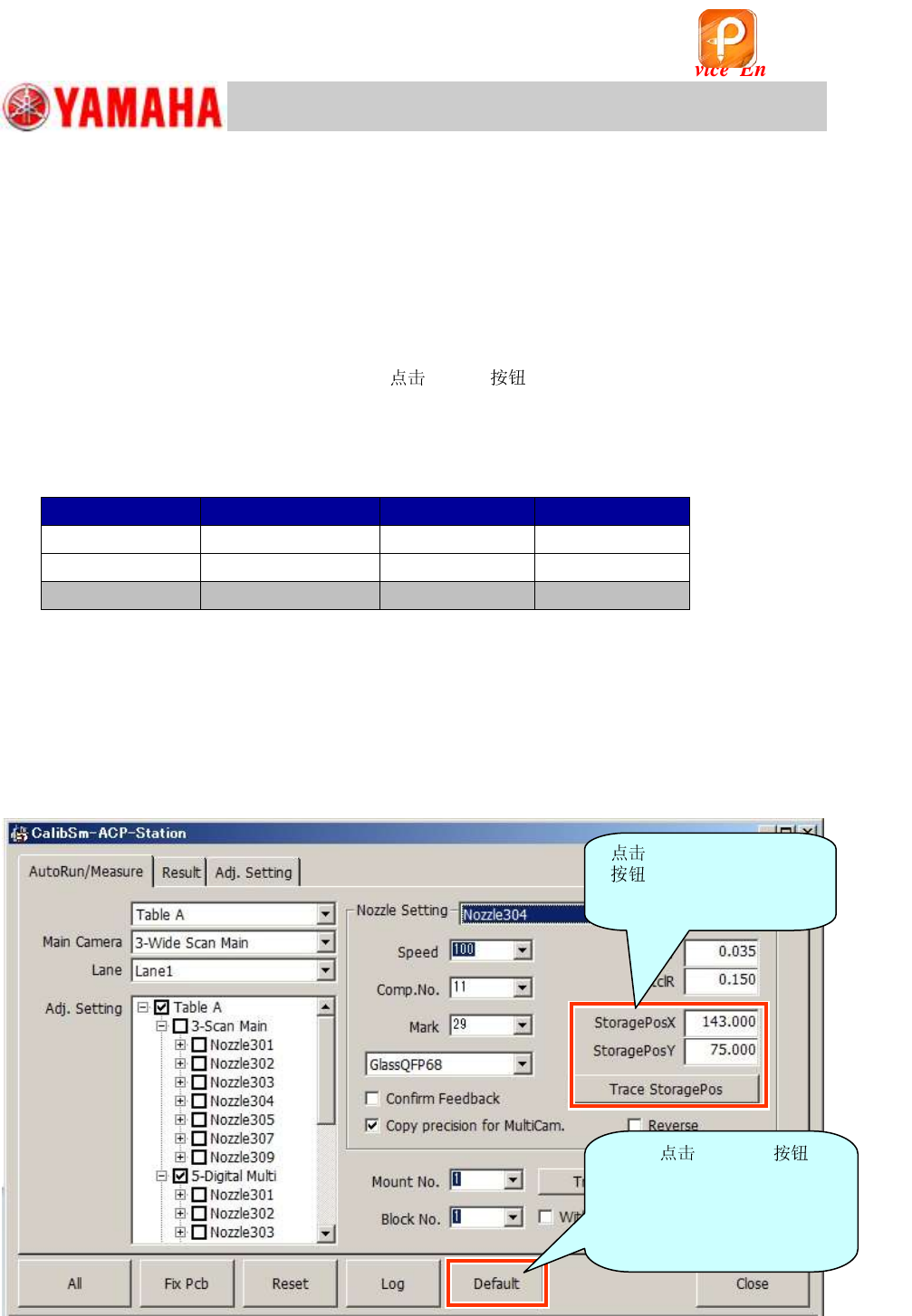
When you lose track of the specified value,
default to change the settings back to
default.
[Specified upper limit value]
*Normally adjustment is NOT performed for the 303 (314) .
QFP
UtclXY
UtclR
304 (315)
68-pin QFP
0.035
0.15
307 (318)
208-pin QFP
0.035
0.15
303 (314)
16-pin QFP
0.035
1.00
Table 32
6. Check the “Storage Pos. XY”.
Even when performing the adjustment with only one type of , the position to temporarily
place the jig ( QFP) needs to be specified somewhere on the station. The position should be
somewhere that does not affect the mounting adjustment. Set the coordinates with reference to the
“Block Offset” value (Do not change the “Board Offset” and the “Block Offset” values). When
performing the adjustment for other s, specify the “StoragePos” of the component to be
used for each .
Figure 89
[Trace Storage]
to check the
coordinates of the storage
position.
If you [Default] ,
the “Storage Pos.”
coordinates are changed
back to the “Storage Pos.”
coordinates of the standard
FAMF station.
该文档是极速PDF编辑器生成,
如果想去掉该提示,请访问并下载:
http://www.jisupdfeditor.com/
For Service Engineer
Service Information
SI1610004E-000= YSM10_Procedures for the adjustments required after installing a machine
67/107
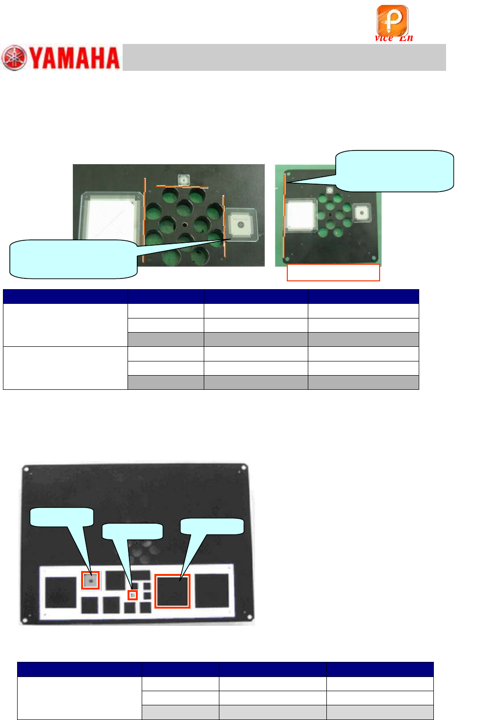
Default strage storage position
The storage position of the QFP is set near the mounting position on the FAMF station as
default.
Set the QFP to be along with the end face of the
10mm holes near the center of the station.
It is the default storage position.
Figure 90
FAMF station
QFP
Storage Pos X (mm)
Storage Pos Y (mm)
Standard (240X170mm)
68-pin
143.0
75.0
208-pin
69.0
75.0
16-pin
110.0
101.5
Small-sized
(100X100mm)
68-pin
73.0
40.0
208-pin
8.0
40.0
16-pin
40.0
66.5
Table 33
Storage position for the FAMF station with the jig sticker
When using the FAMF station with the jig sticker for “Calib Auto”, it is possible to set the QFP
on the specified spot on the sticker to perform the adjustment.
Figure 91
[Storage Pos. XY]
FAMF station
QFP
Storage Pos X (mm)
Storage Pos Y (mm)
Standard station
with the jig sticker
(240x170mm)
68-pin
62.5
34.5
208-pin
147.0
22.5
16-pin
107.0
18.0
Table 34
16-pin QFP
208-pin QFP
68-pin QFP
Set the QFP to be along
with the end face of the
10mm holes on the station.
Set the QFP to be
along with the end face of
the station.
Small FAMF station
该文档是极速PDF编辑器生成,
如果想去掉该提示,请访问并下载:
http://www.jisupdfeditor.com/