YSM10安装调整(eng).pdf - 第58页
For Ser v ice E n gineer Service Information SI1610004E -000= YSM10_Proced ures for the adjustmen ts required after installing a machine 58/107 6.4 Read the board dat a “ MCH_ SETUP ” The coordinate data in the board dat…
For Service Engineer
Service Information
SI1610004E-000= YSM10_Procedures for the adjustments required after installing a machine
57/107
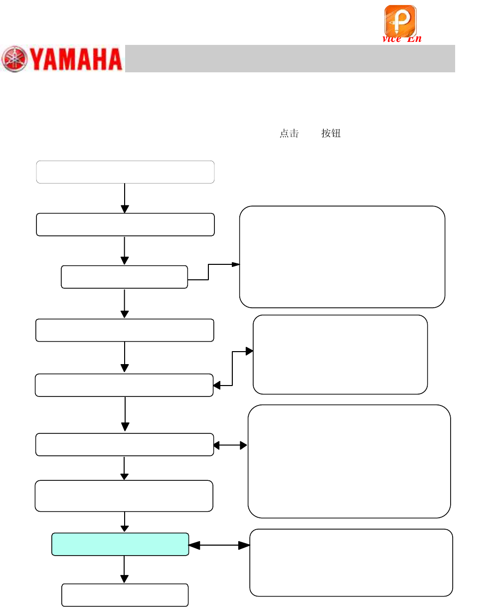
6.3 Flow of the adjustment
Perform initial setup for using the FAMF station (Connect the air supply and wirings for the ejector),
check the settings for the “ACP-Station” adjustment and
[All] to start the adjustment.
Figure 73
Initial setup for the FAMF station
Check the board data
• Block fiducial
• Mounting coordinate
• Mark recognition (Fiducial mark,
QFP mark)
• Part recognition (68-pin QFP)
Start up CalibSm – “ACP-Station”
Run the program
<When the adjustment cannot be
completed properly>
Identify the cause and take appropriate
measures, and perform the adjustment again.
Read the board data (MCH_SETUP)
Check the Total Index
Setting on the right side of the window
Check the Board data
Setting on the left side of the window
Check the setting on the left
side
Main camera
Adjust camera
Adj. Setting and Head
Check the setting on the right
side
Speed
Mark
UtclXY
Storage Pos XY
Block No.
Set the QFP on the storage
position
该文档是极速PDF编辑器生成,
如果想去掉该提示,请访问并下载:
http://www.jisupdfeditor.com/
For Service Engineer
Service Information
SI1610004E-000= YSM10_Procedures for the adjustments required after installing a machine
58/107
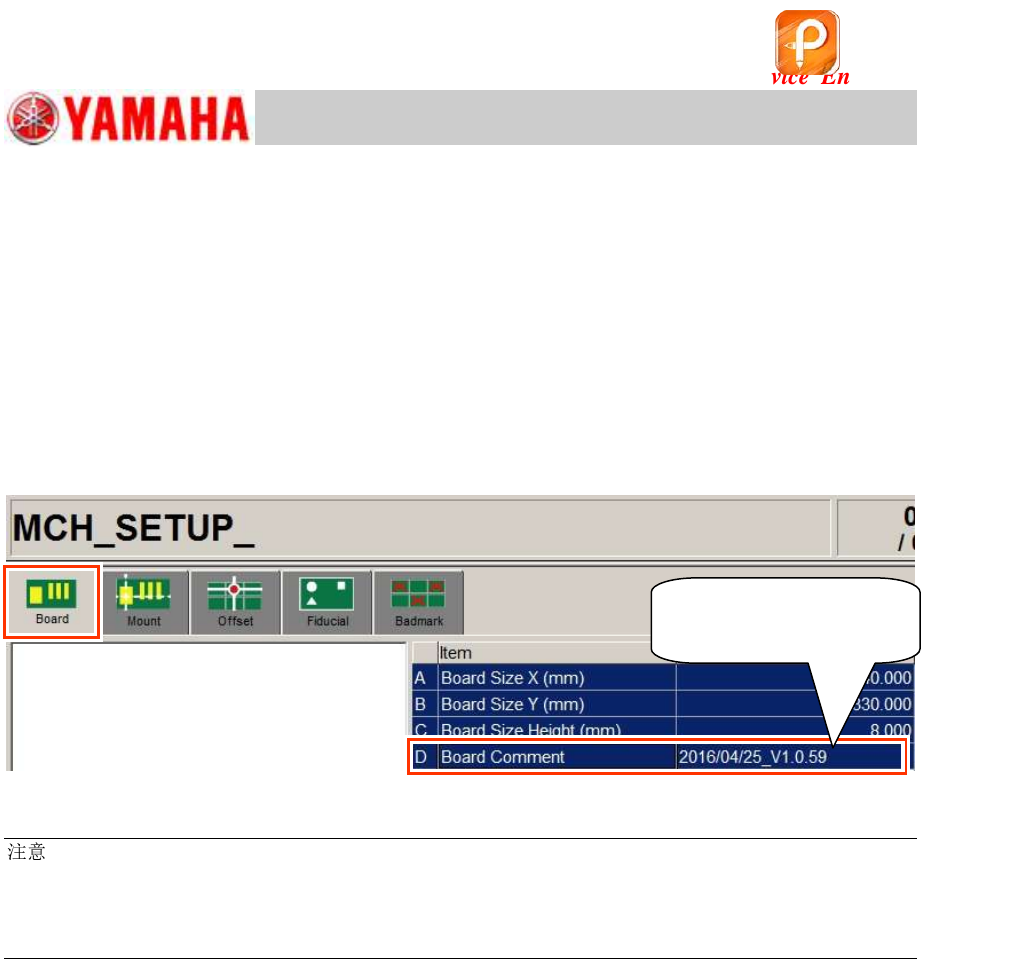
6.4 Read the board data “MCH_SETUP”
The coordinate data in the board data “MCH_SETUP” is used to perform the “ACP-Station”
adjustment in CalibSm.
Check the board data version
Read the board data “MCH_SETUP”.
After reading the data, make sure that the board data version in the “Board Comment” field (on the
[Board]-[Board] window) corresponds to the “ACP-Station” utility.
Required version: V1.058 or later
Figure 74
:
If the version of the read board data is old, copy the data from the folder of the corresponding model in
“PCBDATA” folder in the application installation CD.
(The “MCH_SETUP.ygx” data is shared by all the models.)
Copy the board data for the ACP-Chip adjustment from the same location.
Make sure that the
version is V1.058 or later.
该文档是极速PDF编辑器生成,
如果想去掉该提示,请访问并下载:
http://www.jisupdfeditor.com/
For Service Engineer
Service Information
SI1610004E-000= YSM10_Procedures for the adjustments required after installing a machine
59/107
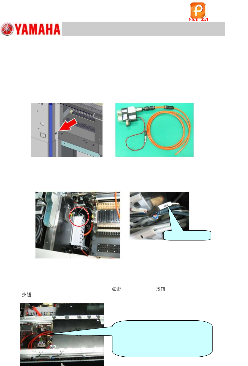
6.5 Initial setup for the FAMF station
Connect the air supply and wiring for the FAMF station.
6.5.1 When using a standard FAMF station
1. Connect the air supply to the ejector.
Connect the air hose of the ejector for the FAMF station (
mm) to the air joint (
mm) at the left
side of the feeder bank.
Figure 75
2. Connect the connector of the ejector.
Take out the harness for driving the ejector “AMF1” from the duct on the left of the feeder bank,
and connect it to the ejector connector.
Figure 76
3. Clamp the FAMF station board.
1) Connect the
6.0 mm air hose from the ejector to the air joint on the back of the station.
2) Change the conveyor width to 170.0mm,
[Main Stopper] and the [Board clamp]
to clamp the station with the board clamp.
Figure 77
AMF1 connector
[Caution]
Make sure that the air hose of the
ejector for the station is located under
the conveyor to avoid interference with
the head.
该文档是极速PDF编辑器生成,
如果想去掉该提示,请访问并下载:
http://www.jisupdfeditor.com/