YSM10安装调整(eng).pdf - 第50页
For Ser v ice E n gineer Service Information SI1610004E -000= YSM10_Proced ures for the adjustmen ts required after installing a machine 50/107 5.6.2 “A CP - Chip” adjustment for the multi camer a 1. Select the “ AutoRun…
For Service Engineer
Service Information
SI1610004E-000= YSM10_Procedures for the adjustments required after installing a machine
49/107
5.6 ACP-Chip adjustment for the Multi camera (Option)
This section describes the procedures of the ACP-Chip adjustment for a YSM10 that is equipped
with the optional Multi camera.
:
Make sure that the “Head Offset (Each camera)” adjustment is performed for all the component
recognition cameras (not only for the main component recognition camera). Otherwise “Camera Acc.
Copy” cannot be performed. See “4.13 “Head Offset XY” adjustment” for the details of the Head offset
adjustment (for each camera).
5.6.1 Camera Acc. Copy
When the machine is equipped with the optional multi camera, perform “Camera Acc. Copy” and
then the ACP-Chip adjustment for the multi camera (5-Digital MultiC, 6-Digital MultiC) after
completing the ACP-Chip adjustment for the scan camera (3-Scan Main).
1. Make sure that the ACP-Chip
adjustment for the scan camera
(3-Scan Main) has been completed.
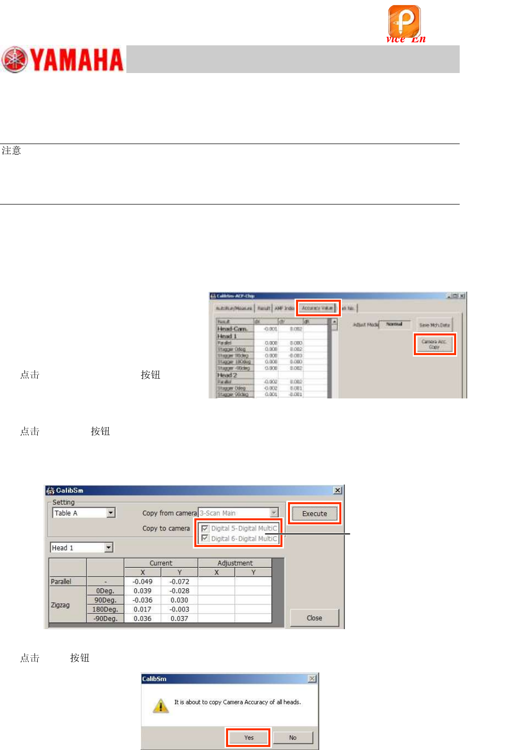
2. Display the “Accuracy Value” tab on
the “ACP-Chip” window.
3.
[Camera Acc. Copy] .
Figure 63
4.
[Execute] on the displayed window and copy the accuracy parameters.
“Copy from camera”: “3-Scan Main”
“Copy to camera”: “Digital 5- Digital MultiC and “Digital 6- Digital MultiC”
Figure 64
5.
[Yes] to perform “Camera Acc. Copy”.
Figure 65
All the sub cameras
are selected as
“Copy to Camera”
automatically.
该文档是极速PDF编辑器生成,
如果想去掉该提示,请访问并下载:
http://www.jisupdfeditor.com/
For Service Engineer
Service Information
SI1610004E-000= YSM10_Procedures for the adjustments required after installing a machine
50/107
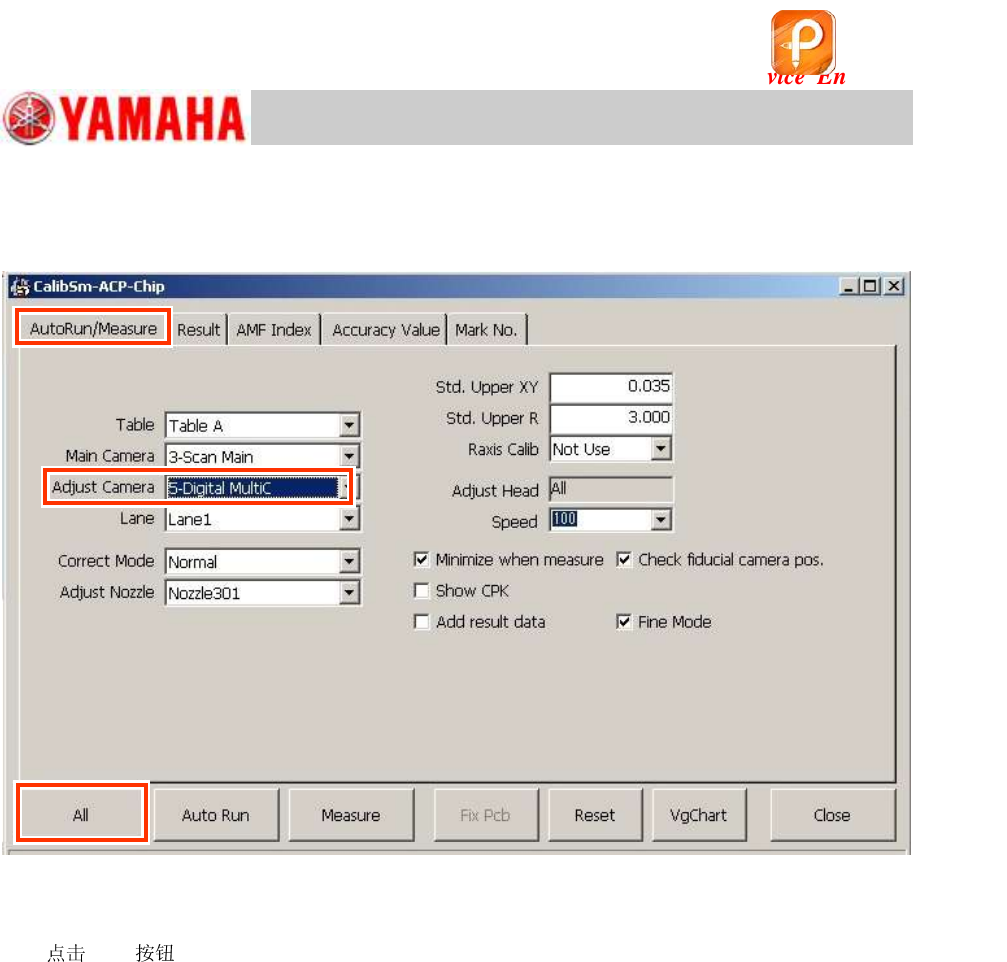
5.6.2 “ACP-Chip” adjustment for the multi camera
1. Select the “AutoRun/Measure” tab on the ACP-Chip window.
Figure 66
2. Change the setting of “Adjust Camera” to “5-Digital MultiC” (Multi camera).
3.
[All] .
Perform the ACP-Chip adjustment for the Multi camera in the same manner as the adjustment for
the Scan camera.
Items to be adjusted
Digital 5(6) _All the heads of the camera (Main ) Precision Zigzag parameter (X, Y)
Digital 5(6) _All the heads except for the Head 1 of the camera (Main )
Precision Parallel parameter (X, Y)
4. Perform the ACP-Chip adjustment for the “6-Digital MultiC” continuously.
If the mahcine is equipped with the multi cameras both on the front and the rear side of it, change
the setting of “Adjust Camera” to “6-Digital MultiC”, and perform the ACP-Chip adjustment.
5. Perform the ACP-Station adjustment.
After completing the ACP-Chip adjustment, perform the ACP-Station adjustment with a 304A
(315A) and a 68-pin QFP.
See “6. “ACP-Station” adjustment (with a QFP and the Multi camera)” for the method.
该文档是极速PDF编辑器生成,
如果想去掉该提示,请访问并下载:
http://www.jisupdfeditor.com/
For Service Engineer
Service Information
SI1610004E-000= YSM10_Procedures for the adjustments required after installing a machine
51/107
5.7 “AMF Index” and “VgChart”
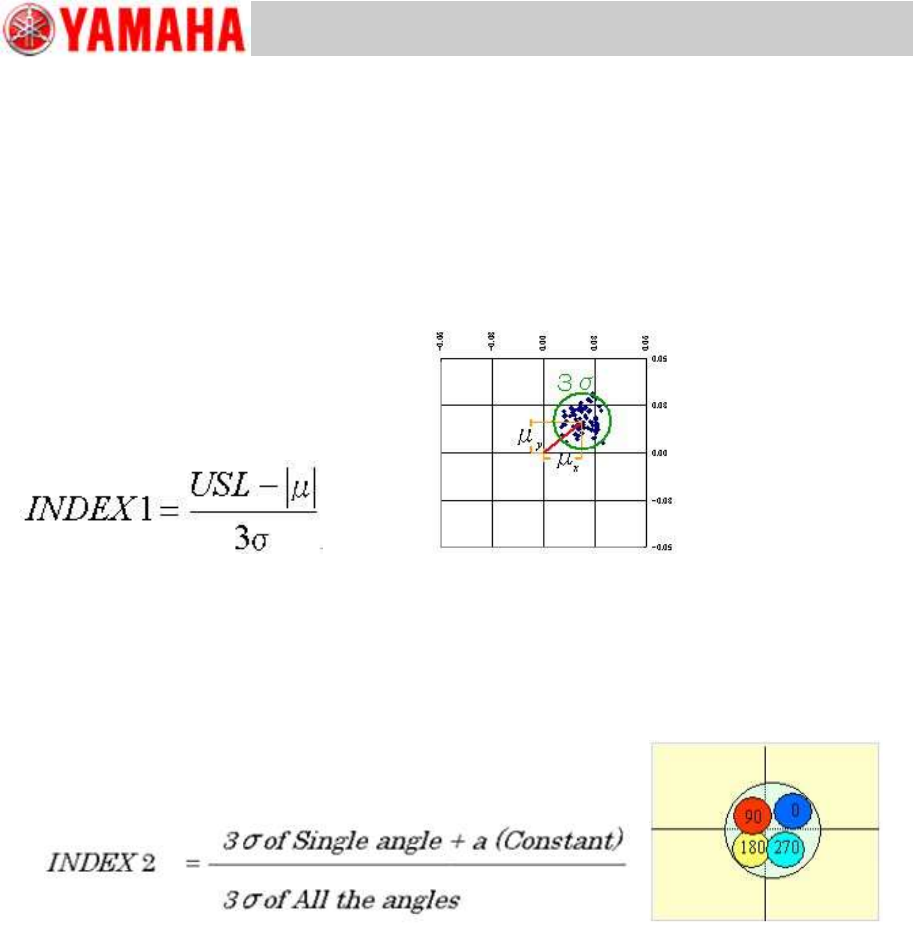
5.7.1 About “AMF Index”
AMF Index 1
INDEX 1 (Total) --- CPK (Process Capability)
It indicates if the value obtained by the formula below meets the upper limit standard value (USL).
“Deviation with single head at a single angle (3σ) + “Average distance from the center (
)”
Figure 67
AMF Index 2
It quantifies the variation of mounting position at a single angle against the variations of all the four
angles (0, 90,180 and 270 degrees).
If it falls below 1.0, feeding back the correctio values is effective.
Figure 68
Only the “
” value can be improved by the feedback.