YSM10安装调整(eng).pdf - 第92页
For Ser v ice E n gineer Service Information SI1610004E -000= YSM10_Proced ures for the adjustmen ts required after installing a machine 92/107 11.3.3 Scan camera – “Lightness” adj ustment W hen performing the “ Lightnes…
For Service Engineer
Service Information
SI1610004E-000= YSM10_Procedures for the adjustments required after installing a machine
91/107
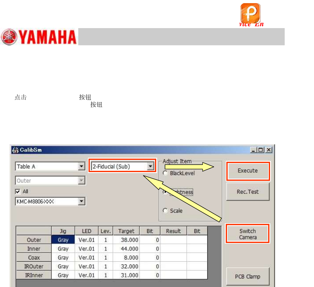
If the machine is equipped with the sub fiducial camera (Option)
After completing the adjustment for the “1-Fiducial (Main)” camera, perform the adjustment for the
“2-Fiducial (Sub)” camera continuously.
7. [Switch Camera] .
When the [Switch Camera]
has been tapped, the sub fiducial camera (2-Fiducial (Sub))
moves to above the light adjuster that is being caught by the main fiducial camera (1-Fiducial
(Main)).
After the sub fiducial camera moves to the position, the camera name is switched from “1-Fiducial
(Main)” to “2-Fiducial (Sub)” automatically.
Figure 134
8. Check the camera type, and perform the “Lightness” adjustment.
Check if the values in the “Result” and the “Bit” fields meet the specification, and save the data.
If the values fall within the specification, fill in the values on the check sheet.
该文档是极速PDF编辑器生成,
如果想去掉该提示,请访问并下载:
http://www.jisupdfeditor.com/
For Service Engineer
Service Information
SI1610004E-000= YSM10_Procedures for the adjustments required after installing a machine
92/107
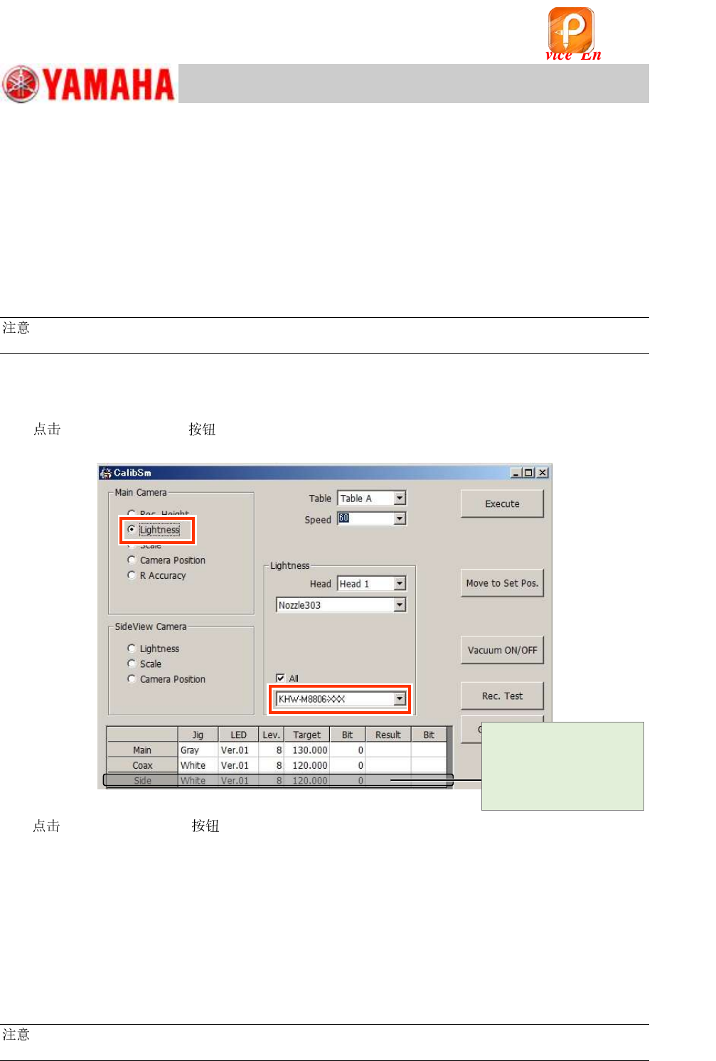
11.3.3 Scan camera – “Lightness” adjustment
When performing the “Lightness” adjustment for the Scan camera, adjust the main camera and the
side view camera separately.
Light adjuster
When performing the adjustment for the main camera, make sure to use the light adjuster
dedicated to the Scan camera (11mm square) in order to avoid the interference with the scan unit.
No jigs are required for the “Lightness” adjustment of the side view camera.
Perform the adjustment with a 301A (312A) or a 302A (313A) attached to the head.
:
See “2.1 Jigs for the “Lightness” adjustment of the cameras” for the types of the light adjusters.
“Lightness” adjustment for the Main camera
1. Select “Lightness” from “Main Camera”.
[010 Scan camera] on the CalibSm main menu and select “Lightness” from “Main
Camera”.
Figure 135
2. [Move to Set Pos.] to change the to 303A (314A) .
If the machine is equipped with an ANC, the of the head to be adjusted is changed to
“ 303A (314A)”, and the head moves to above the front-side feeder bank.
If the machine is NOT equipped with an ANC, the head to be adjusted moves to above the
front-side feeder bank.
Put the machine into the “Emergency stop” state, and attach the 303A (314A) to the
head by hand.
3. Select the light adjuster.
The target values vary depending on the light adjusters to be used. Make sure to select the part
number of the light adjuster that is actually used for the adjustment.
:
See “2.1 Jigs for the “Lightness” adjustment of the cameras” for the types of the light adjusters.
[Cancel] the
adjustment process for
the adjustment of the
Side light of the Main
camera.
该文档是极速PDF编辑器生成,
如果想去掉该提示,请访问并下载:
http://www.jisupdfeditor.com/
For Service Engineer
Service Information
SI1610004E-000= YSM10_Procedures for the adjustments required after installing a machine
93/107
4. Set the light adjuster to the .
Make the head suck the light adjuster with its gray surface facing down.
Caution:
Set the light adjuster in the center of the so that it does not interfere with the Scan camera.
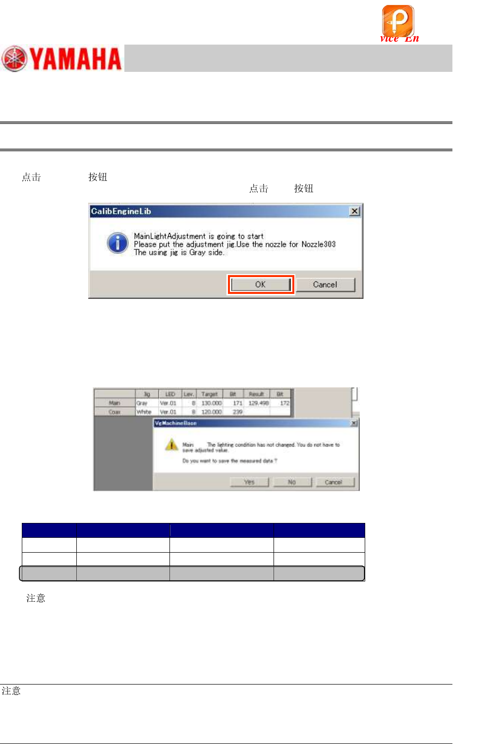
5. Start the “Lightness” adjustment for the main light.
[Execute] to display the following dialog box.
Make sure that the light adjuster is set properly and [OK] to start the adjustment.
Figure 136
6. Save the adjusted data.
When the adjustment is completed, a dialog box appears asking you to save the data.
Make sure that the values in the “Result” and the “Bit” fields fall within the specification, and save
the data.
If the values fall within the specification, fill in the values on the check sheet.
Figure 137
[Specified value]
Jig color
Tolerance
Bit value
Main
Gray
Target value +/- 2
128 ~ 448
Coax
White
Target value +/- 2
128 ~ 448
Side
White
Target value +/- 2
128 ~ 448
Table 41
[
]
When the Bit value does not meet the specification, check the following:
・ Is the correct light adjuster selected?
・ Is the adjuster clean? If it is not, clean it with alcohol.
・ Is the lighting environment affecting the adjustment result?
・ Is the lighting condition normal? (Are all the LEDs lit?)
:
As the upper limit of the specified Bit value is the warning value, the adjustment can be completed
properly even when the value exceeds the specified value.
If the measured result exceeds 448 (the 7/8 of the limit value), it may attribute to the deterioration of the
lighting device. It is recommended to replace the light. (Limit value of the Bit value: 511)
NOT USED (Cancel the adjustment process)
该文档是极速PDF编辑器生成,
如果想去掉该提示,请访问并下载:
http://www.jisupdfeditor.com/