YSM10安装调整(eng).pdf - 第79页
For Ser v ice E n gineer Service Information SI1610004E -000= YSM10_Proced ures for the adjustmen ts required after installing a machine 79/107 7.2.3 Plate check After adjusting the p ickup position of all the sect ions,…
For Service Engineer
Service Information
SI1610004E-000= YSM10_Procedures for the adjustments required after installing a machine
78/107
7.2.2 Feeder Pickup position Z adjustment
Measure the height of the datum feeder specified per section.
Although the datum head (Head 1) is basically used for the measurement, if the measurement
cannot be performed with it, other head is automatically selected.
Use a type 302A or a type 313A for the measurement.
If the machine is not equipped with the station (ANC), attach the to the head by
hand.
1. Select the section to be measured.
Tick the checkbox of the section to be measured.
2. Set the jig.
Set the jig to the position (number) shown in the ”Tool Set No” field in “Section Info”.
(If the measurement cannot be performed with the default setting, change the “Tool Set No.”.)
3.
[ZExecute] .
Check the measurement condition set as default (Offset value for each item, Unit Z, Speed, and so
on) and make sure that they are appropriate, and then
[ZExecute] .
The height of the upper surface of the jig is measured automatically.
该文档是极速PDF编辑器生成,
如果想去掉该提示,请访问并下载:
http://www.jisupdfeditor.com/
For Service Engineer
Service Information
SI1610004E-000= YSM10_Procedures for the adjustments required after installing a machine
79/107
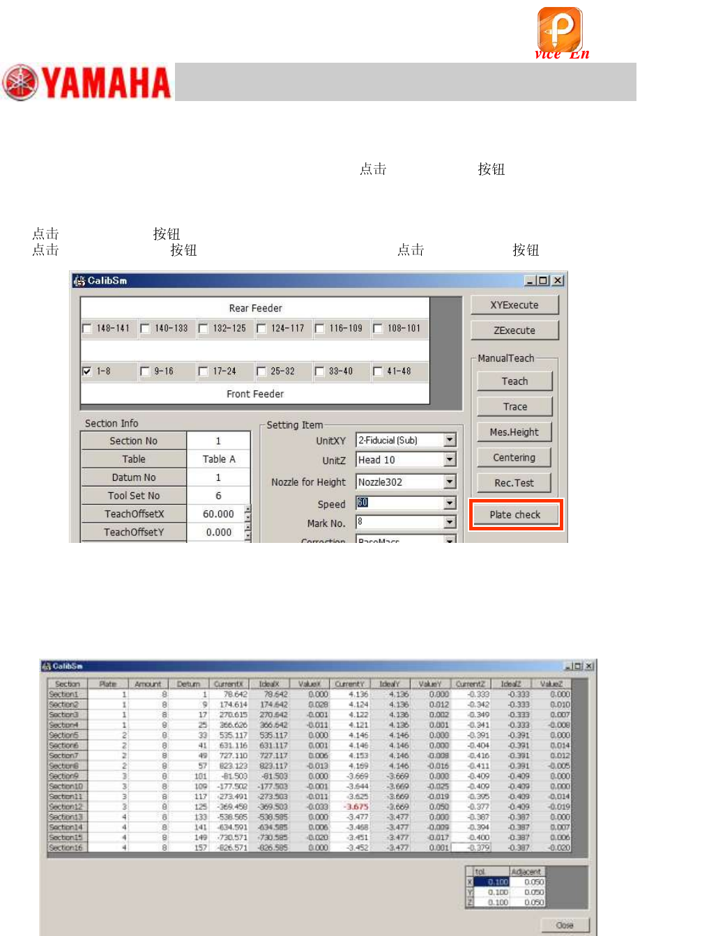
7.2.3 Plate check
After adjusting the pickup position of all the sections,
[Plate Check] to check if the
pickup positions have been adjusted properly.
If any of the coordinate values does not meet the specification, the color of the value changes.
1. [Plate check] on the “FeederPos” window.
[005 FeederPos] on the CalibSm main menu and [Plate check] .
Figure 115
2. Check the coordinate data.
The adjusted coordinate data of all the sections are displayed. If there is any value that changes
the color, it indicates that the coordinate does not meet the specification.
Make sure that the jig is set properly and its set position is appropriate, and then perform the
adjustment again.
Figure 116
[“Adjacent”]
The offset amount of the coordinates between the adjacent sections where the simultaneous
pickup may occur is checked. (When an error occurs, the values turn red.)
[“tol”]
In reference to the first section of each feeder plate, the accumulated offset amount of the pickup
positions in the table is checked. (When an error occurs, the values turn yellow.)
该文档是极速PDF编辑器生成,
如果想去掉该提示,请访问并下载:
http://www.jisupdfeditor.com/
For Service Engineer
Service Information
SI1610004E-000= YSM10_Procedures for the adjustments required after installing a machine
80/107
3. When an error occurs, check the following.
・ Are the settings of the tolerance appropriate?
Item
Specified value
“tol”
0.100
“Adjacent”
0.050
Table 38
・ Was teaching performed properly?
・ Is the jig secured properly? If it is not, perform teaching again.
・ Is the feeder plate parallel to the X-axis? If it is not, adjust the position mechanically.
・ If the value does not fall within tolerance, change the position to set the jig in the same
section.
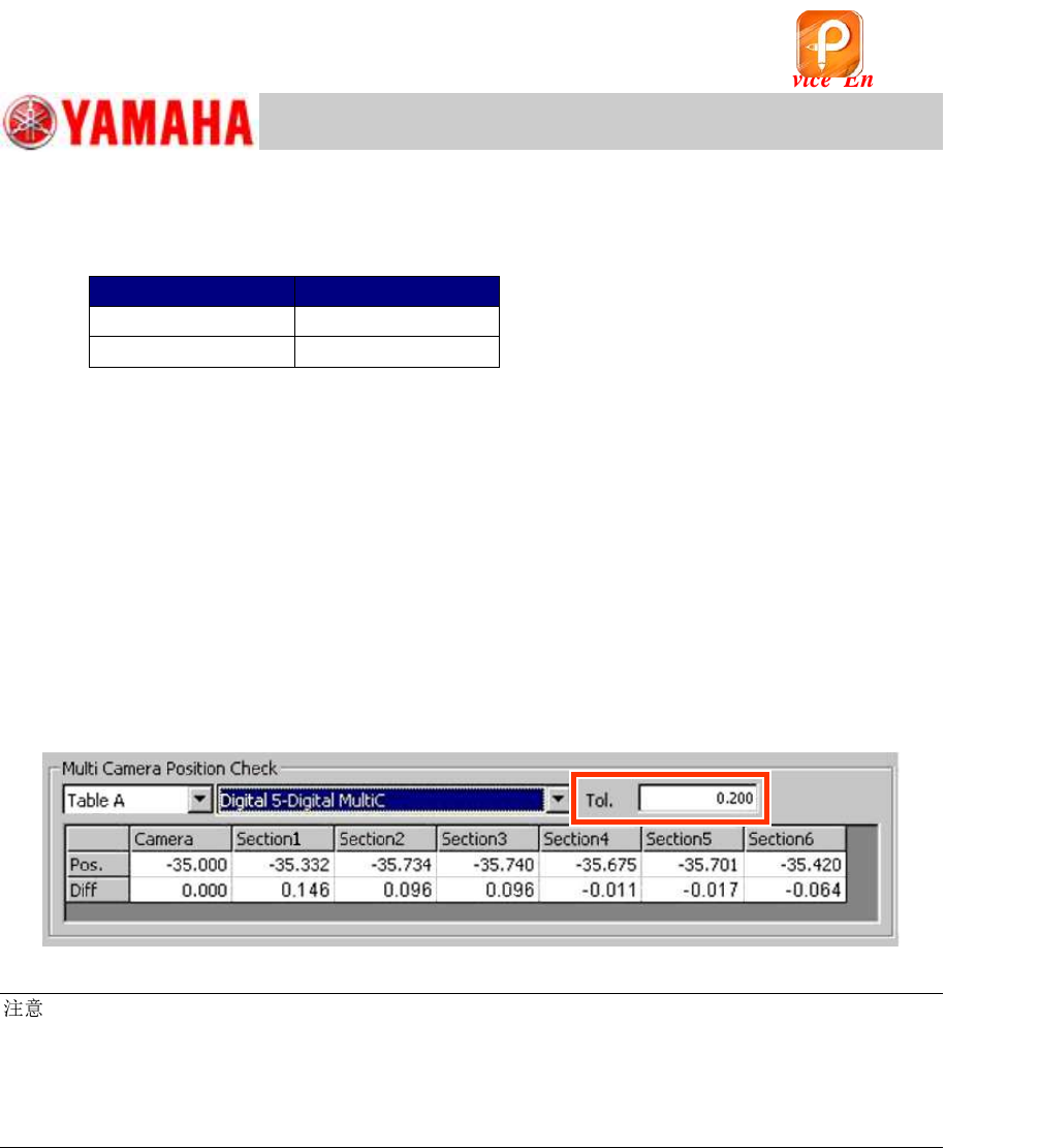
4. Check the position of the multi camera.
The Y-coordinate of the Multi camera center and the Y-coordinate of the pickup position are set in
alignment with each other. The difference between the Y coordinates is displayed.
If it exceeds the tolerance (0.2mm), the field turns red.
If the value exceeds the tolerance, adjust the mounting position of the Multi camera.
Figure 117
:
~ “Multi camera Position Check” ~
When the Multi camera is installed between the feeder plates, the “Feeder plate offset Y ” and the
Y-coordinate of the Multi camera center are set in alignment with each other.
If the position shift of the Y-coordinate is large, the time from the point where a component is picked up
to the point where it is recognized by the Multi camera may slightly delay.
该文档是极速PDF编辑器生成,
如果想去掉该提示,请访问并下载:
http://www.jisupdfeditor.com/