YSM10安装调整(eng).pdf - 第53页
For Ser v ice E n gineer Service Information SI1610004E -000= YSM10_Proced ures for the adjustmen ts required after installing a machine 53/107 5.7.3 How to a naly ze the “ VgCha rt ” Refer to the followi ng for the typi…
For Service Engineer
Service Information
SI1610004E-000= YSM10_Procedures for the adjustments required after installing a machine
52/107
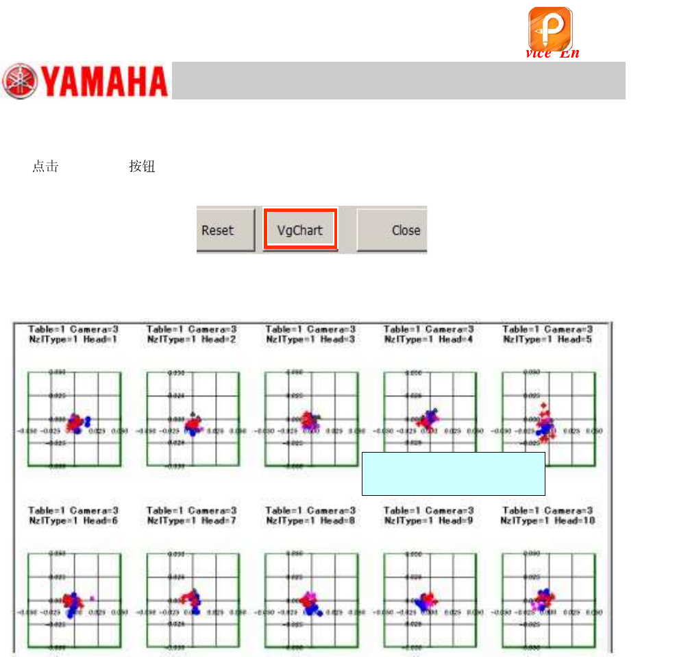
5.7.2 Check the “VgChart” window
1.
[VgChart] .
The chart window is automatically created.
Figure 69
2. Check the mounting state for each head on the chart window.
Figure 70
<When the “AMF index 1” value falls below 1.0>
Check the chart window to determine which head is the causal factor that the “AMF Index 1” does
not meet the specification.
Analyze the chart and perform the further adjustment if needed.
* See “How to analyze the “VgChart”” for how to interpret the graphs.
* See “11.Basic adjustments required when “AMF index 1” falls below 1.000” for the adjustment
procedure.
Double-tap on the graph to
display the details.
该文档是极速PDF编辑器生成,
如果想去掉该提示,请访问并下载:
http://www.jisupdfeditor.com/
For Service Engineer
Service Information
SI1610004E-000= YSM10_Procedures for the adjustments required after installing a machine
53/107
5.7.3 How to analyze the “VgChart”
Refer to the following for the typical charts of the adjustment result
and how to take measures.
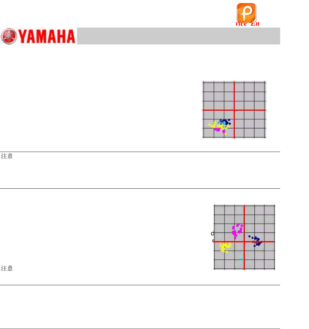
A. If the “XY offset shift” is found in the mounting result data
What is “XY offset shift”?
The components are mounted with deviation to the same direction
in all angles, as can be seen in Figure 71.
In this case, the “Index 2” value may be 1.00 or above.
Figure 71
:
Even when the “Index 1” value falls below 1.000, there is a case that the mounting positions are close
to one another, and are all deviated in the same way.
When this symptom occurs, there is a possibility that the positional coordinates of the fiducial camera
has been changed. Make sure that the camera is positioned properly before performing feedback.
B. If the mounting result data spreads in the X and Y directions
The mounting result data may spread in the X and Y directions in different ways depending on
the mounting angle as can be seen in Figure 72.
The “Index 2” value varies depending on the pattern of the mounting result data.
When this symptom occurs, any of the basic data may have been changed.
When the symptom still occurs even after feeding back the correction values, perform the basic
adjustments again.
Figure 72
:
When the “Index 1” value is 1.000 or above and the “Index 2” value falls below 1.000, there is a case
that the mounting result data slightly spreads in the X and Y directions. In this case, feed back the
correction values instead of readjusting the basic data.
When any problem related to mounting inaccuracy is found, take appropriate measures and perform
the readjustment.
Items of the basic data to be adjusted
Perform the adjustment for the following items:
・ Fiducial camera - “” adjustment
・ Scan camera - “” adjustment
・ “Head Offset Z” adjustment
When the machine is equipped with the Multi camera
After completing the basic adjustments for the scan camera, the basic data of the Multi camera
needs to be adjusted.
Perform the “” adjustment for the Multi camera.
该文档是极速PDF编辑器生成,
如果想去掉该提示,请访问并下载:
http://www.jisupdfeditor.com/

For Service Engineer
Service Information
SI1610004E-000= YSM10_Procedures for the adjustments required after installing a machine
54/107
C. If the variation and abrupt shift are found in the mounting result
If the mounting state is unstable, accurate measurement data cannot be obtained. Therefore, the
mounting result cannot be improved no matter how many times the feedback is performed.
Identify the cause of the problem and take appropriate measures.
[Items to be checked]
Is the board clamped properly?
Does the component reach the board surface properly when it is being mounted?
Is the mark recognition performed in the stable condition?
(The mark should be clean and the mark information should be correct.)
Is the component supply unit feeding the component properly, and the components are
picked up properly?
Are the components recognized properly?
Is the clean or secured properly?
Are the lens of the camera and the lighting part clean?
Is the camera mounted to the machine properly?
If any problems are detected, take appropriate measures and perform the ACP-Chip adjustment
again.
When performing the adjustment of the board edge clamp unit, the data of the following items
may need to be adjusted.
[Items to be adjusted]
“PCB Height”
“Head Offset Z”
Caution:
The “” adjustment for the fiducial camera needs to be performed only when the AMF Index 1 falls
below 1.000 with the main camera (for recognizing components).
If the AMF Index 1 falls below 1.000 when checking the mounting accuracy with the sub camera, the
adjustment is not required.
该文档是极速PDF编辑器生成,
如果想去掉该提示,请访问并下载:
http://www.jisupdfeditor.com/