00197042-04_SM_X-Serie-S_Customer_EN.pdf - 第120页
4 Electrics and control system 4.5 Indicator lamp 120 Service Manual SIPLACE X-Serie S 06/2019 Removal ► Switch off the machine, disconnect it from the power supply and secure it to prevent unauthorized reactivation. 1.2…
4 Electrics and control system
4.5 Indicator lamp
Service Manual SIPLACE X-Serie S 06/2019 119
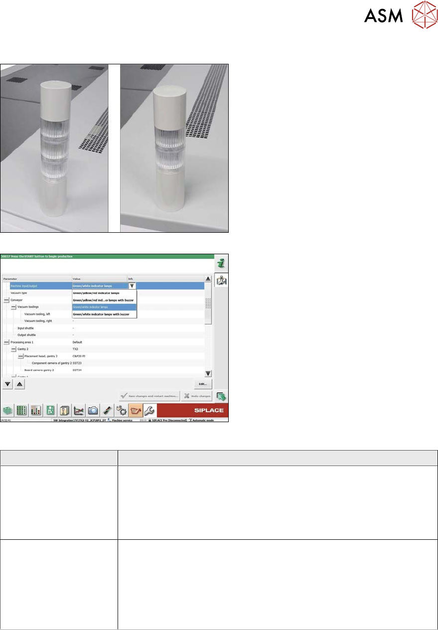
Two/three color indicator lamp
Fig.142: Three/two color indicator lamp
Fig.143: Setting the three/two color indicator lamp
The indicator lamp can either be configured
as a two or three color version:
1. Three color indicator lamp (red/yellow/
green)
2. Two color indicator lamp (white/green)
To convert from two to three color (or vice
versa), fit the relevant LED modules and set
the correct option in the machine configura-
tion.
Variant Parts
Two color variant
(green/white)
●
Tower light standard series LR5 (basic module including cable)
[03148080‑xx]
●
Buzzer module LR5-BW 50mm [03162667‑xx]
●
LED module LR5-E-GZ 50mm green, transparent [03162663‑xx]
●
LED module LR5-E-CZ 50mm white, transparent [03162666‑xx]
Three color variant
(green/yellow/red)
●
Tower light standard series LR5 (basic module) [03148080‑xx]
(replaces [03103121‑xx])
●
Buzzer module LR5-BW 50mm [03162667‑xx]
●
LED module LR5-E-GZ 50mm green, transparent [03162663‑xx]
●
LED module LR5-E-YZ 50mm yellow, transparent [03162665‑xx]
●
LED module LR5-E-RZ 50mm red, transparent [03162664‑xx]
4 Electrics and control system
4.5 Indicator lamp
120 Service Manual SIPLACE X-Serie S 06/2019
Removal
► Switch off the machine, disconnect it from the power supply and secure it to prevent
unauthorized reactivation.
1.2 "Preparatory work..." [}16]
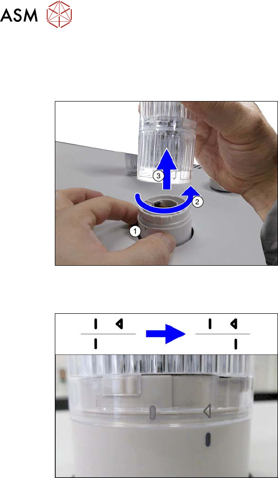
Fig.144: Removing the indicator lamp
► Hold the base(1) of the indicator lamp
tightly, so that it does not rotate.
► Turn the top section of the indicator
lamp approx. 2cm anti-clockwise(2)
and then take the indicator lamp up and
off(3).
Installation
Fig.145: LED module with housing
Assembling the modules
► When assembling the modules, pay at-
tention to the line and arrow markings.
► First fit the modules together so that
the lines are on one another.
► Now turn the top modules approx. 2cm
clockwise, until the arrow is over the
line.
Hold the base tightly during this, so that
it does not turn.
4 Electrics and control system
4.6 Replacing the monitor/monitor holder
Service Manual SIPLACE X-Serie S 06/2019 121
4.6 Replacing the monitor/monitor holder
Parts, equipment and tools
●
Monitor SCD1520-TDC [03078913-xx]
●
Monitor holder [03042042‑xx]
●
Standard tooling
●
Torx screwdriver ESD 1.0-5.0 Nm [03078400-xx]
●
Bit holder for TorqueVario screwdriver [03078706-xx]
Overview
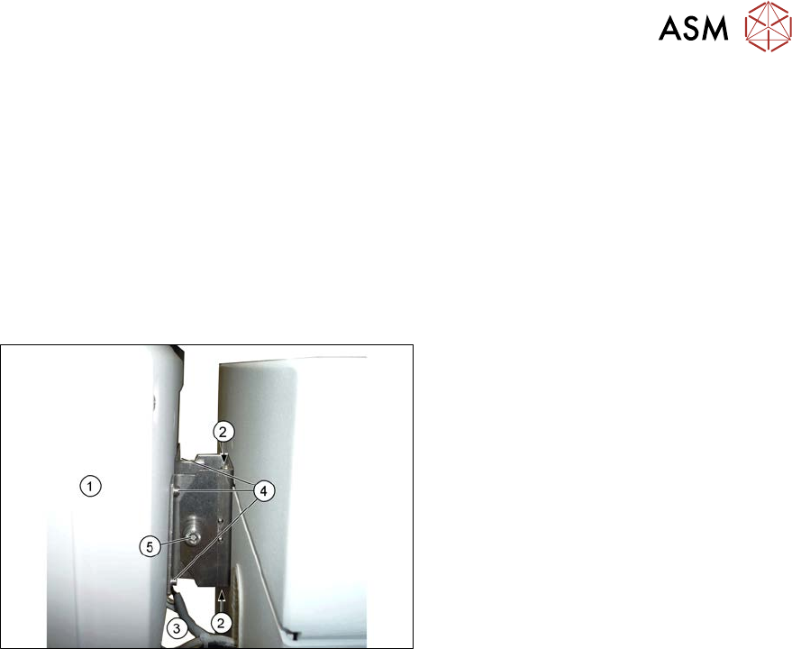
Fig.146: Overview of monitor
1. Monitor
2. Screws fastening the monitor holder to
the machine
3. Monitor connections
4. Screws fastening the monitor to its
holder
5. Screw (joint)
(torque 4.5Nm)
Removal
► Switch off the machine, disconnect it from the power supply and secure it to prevent
unauthorized reactivation.
1.2 "Preparatory work..." [}16]
► Unplug all connections to the monitor. You may want to mark their positions, to make clear as-
signment easier later on.
► Loosen the upper and lower screws fastening the monitor bracket to the machine and lift the
monitor and its bracket out of the keyholes.
► Remove the four screws fastening the monitor to its bracket and then remove the monitor
bracket.
Installation
► Follow the removal instructions in reverse order for installation. Also observe the following
instructions:
– First tighten the screw (joint) with a torque of 4.5Nm.