00197042-04_SM_X-Serie-S_Customer_EN.pdf - 第76页
3 Power supply 3.4 Power supply and transformer module (up to serial number Gxxx) 76 Service Manual SIPLACE X-Serie S 06/2019 Removal ► Switch off the machine, disconnect it from the power supply and secure it to prevent…
3 Power supply
3.4 Power supply and transformer module (up to serial number Gxxx)
Service Manual SIPLACE X-Serie S 06/2019 75
3.4.20 Replacing the Motor Protection Release Block (PKZ2)
NOTICE
Old version [00342494-xx]
This version of the motor protection switch has been discontinued and may need to be re-
placed with the new version "motor protection switch PKE32/XTU-32 assembly 3-
pin" [03098183-xx].
► Read also section 3.4.21 "Replacing the motor protection switch PKE32/
XTU-32" [}78] and the technical information "Product discontinuation of "Motor cir-
cuit breaker PKZ2 basic machine, 3-pin" [00342494-xx]" [TI2015-03D02] [EN:
TI2015-03E02].
Parts, equipment and tools
If you have supply voltages of 3x208 V~ and 3x230 V~, you will need to use the motor protection
trip block ZM-32-PKZ2 [00342496-xx].
●
Motor protection trip block ZM-16-PKZ2 [00342495-xx] (default)
●
Motor protection trip block ZM-32-PKZ2 [00342496-xx] (US version)
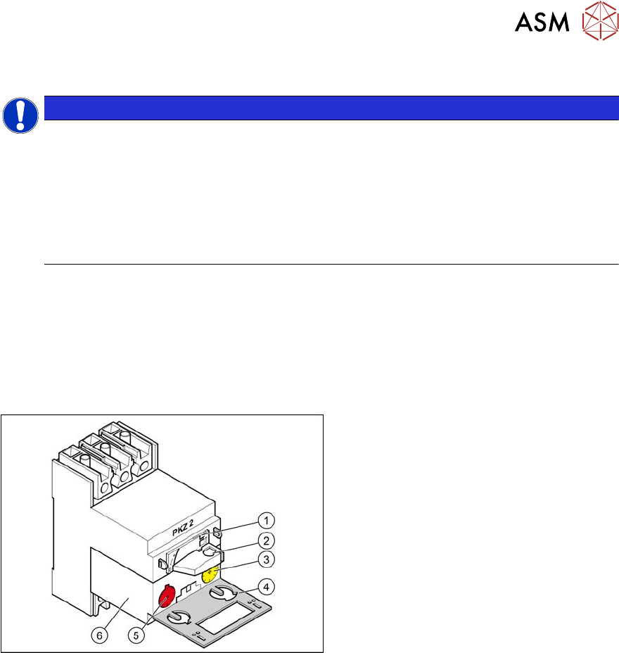
Overview
Fig.77: Motor protection switch
1. Locking tab
2. Rotary switch
3. Trigger threshold for overcurrent
(yellow setting disk)
4. Protective flap
5. Trigger threshold for short-circuit
current (red setting disk)
6. Motor protection trip block
3 Power supply
3.4 Power supply and transformer module (up to serial number Gxxx)
76 Service Manual SIPLACE X-Serie S 06/2019
Removal
► Switch off the machine, disconnect it from the power supply and secure it to prevent
unauthorized reactivation.
1.2 "Preparatory work..." [}16]
► Before you start working, check the power supply for absence of voltage and observe the
waiting times!
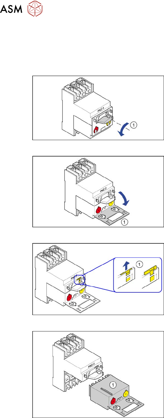
Fig.78: Position "0"
► Turn the switch(1) anticlockwise to the
position"0"
Fig.79: Swing open
► Open the protective flap(1).
Fig.80: Locking tab
► Use a screwdriver to push the yellow
locking tab(1) upwards.
Fig.81: Motor protection trip block
► Pull the motor protection trip block(1)
out.
3 Power supply
3.4 Power supply and transformer module (up to serial number Gxxx)
Service Manual SIPLACE X-Serie S 06/2019 77
Installation
Motor protection trip block settings
Motor protec-
tion trip
block
Yellow setting disk
for overcurrent trig-
ger threshold
Red setting disk for
short-circuit current
trigger threshold
X-Series/SX4/DX4 for 3x208V~
+/‑5% (USversion)
ZM-32-PKZ2 24 A 375 A
X-Series/SX4/DX4 for 3x400V~
+/‑5%
ZM-16-PKZ2 16 A 200 A
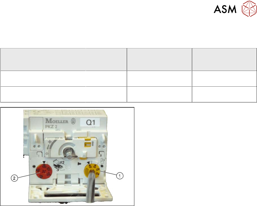
Fig.82: Motor protection trip block – settings
► Check the trigger threshold for overcur-
rent (yellow setting disk(1)).
► Check the trigger threshold for short-
circuit current (red setting disk(2)).
► Insert the motor protection trip block.
► Push the yellow locking tab down-
wards.
► Close the gray protective flap.
► Turn the rotary switch clockwise as far
as the stop.