00197042-04_SM_X-Serie-S_Customer_EN.pdf - 第255页
7 Conveyor 7.7 Clamping Plate, Clamping Rails and Belt Guidance Service Manual SIPLACE X-Serie S 06/2019 255 7.7 Clamping Plate, Clamping Rails and Belt Guidance 7.7.1 Replacing the Clamping Plate, Spacer Disks and Tensi…
7 Conveyor
7.6 Conveyor Belt, Belt Drive and Hexagonal Shaft
254 Service Manual SIPLACE X-Serie S 06/2019
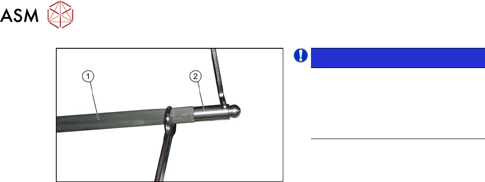
Fig.322: Ball studs on the hexagonal shafts
NOTICE!
Many tasks on the conveyor require
you to simply move the hexagonal
shafts instead of removing them. In
these cases, you generally do not
need to dismantle the ball studs on the
ends of the hexagonal shafts.
.
► Unscrew the two ball studs (2) from the
two ends of the hexagonal shaft (1)
(fork wrench size 8 and10). This
shortens the shaft and makes it easier
to handle.
► Unthread the hexagonal shaft.
Installation
► Follow the removal instructions in reverse order for installation. Also observe the following
instructions:
– Once you have loosened the ball studs of the hexagonal shafts, tighten these with a
torque of 14 Nm.
– Make sure that the hexagonal shafts are not damaged by the tool.
– Do not tighten the screws fastening the hexagonal shaft holder too much yet.
– Check whether the tape drive and the drive unit are aligned correctly to one another.
To do this, push the conveyor sides together until you can still just reach the fastening
screws. Check the conveyor drive for ease of movement by turning the hexagonal shaft.
You may need to loosen the conveyor drive again and then reset it.
7 Conveyor
7.7 Clamping Plate, Clamping Rails and Belt Guidance
Service Manual SIPLACE X-Serie S 06/2019 255
7.7 Clamping Plate, Clamping Rails and Belt Guidance
7.7.1 Replacing the Clamping Plate, Spacer Disks and Tension Spring
Parts, equipment and tools
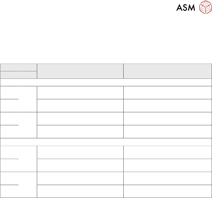
Select the clamping unit needed (clamping plate):
Side panel PA1 PA2
DC SC
SIPLACE X4i S, X4i S micron
A Fixed,
right
Clamping unit A/C PA1 assembly
SX4a [03094044-xx]
Clamping unit PA A/C assembly SXa
[03098833-xx]
B Clamping unit B/D PA1 assembly
SX4a [03094093-xx]
Clamping unit PA B/D assembly SXa
[03098837-xx]
C Fixed,
left
Clamping unit A/C PA1 assembly
SX4a [03094044-xx]
Clamping unit PA A/C assembly SX1a
[03092002-xx]
D Clamping unit B/D PA1 assembly
SX4a [03094093-xx]
Clamping unit PA B/D assembly SX1a
[03092222-xx]
SIPLACE X4 S, X3 S, X2 S, X4 S micron
A Fixed,
right
Clamping unit PA B/D assembly SXa
[03098837-xx]
Clamping unit PA A/C assembly SXa
[03098833-xx]
B Clamping unit PA A/C assembly SXa
[03098833-xx]
Clamping unit PA B/D assembly SXa
[03098837-xx]
C Fixed,
left
Clamping unit PA B/D assembly SXa
[03098837-xx]
Clamping unit PA A/C assembly SX1a
[03092002-xx]
D Clamping unit PA A/C assembly SXa
[03098833-xx]
Clamping unit PA B/D assembly SX1a
[03092222-xx]
●
Lubricant Unisilikon L 250 L 60g tube [00310259Sxx]
●
Flashlight, if needed
●
If needed, tension spring (2x per clamping plate):
These can be replaced separately from the clamping plate.
– Spring PA assembly with bushings and screws SXa. [03088949-xx] or
– Tension spring RZ-057KI [03088940-xx] (without bushings and screws)
●
Spacer disks, if needed:
:When replacing a clamping plate, we recommend that you also replace the spacer disks at
the same time. However, these can also be replaced independently of the clamping plate:
– Shim for clamping plate [03091791-xx] (8x per clamping plate)
– Disk for clamping plate [03091711-xx] (8x per clamping plate)
7 Conveyor
7.7 Clamping Plate, Clamping Rails and Belt Guidance
256 Service Manual SIPLACE X-Serie S 06/2019
Overview
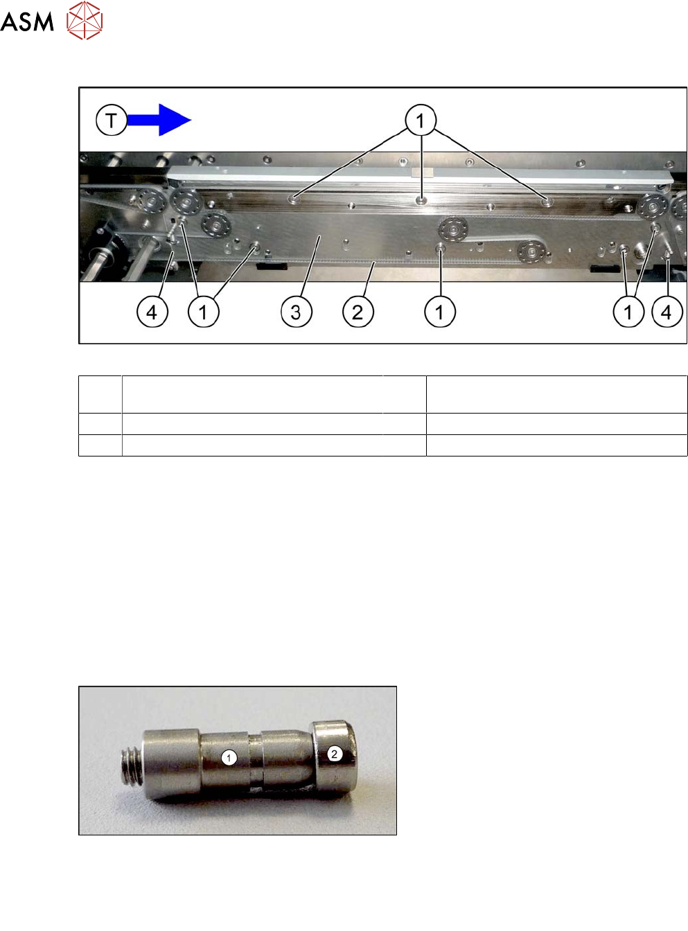
Fig.323: Clamping plate (using example of SIPLACE SX1/SX2)
1 Eight screws fastening the clamping
plate
2 Toothed belt
3 Clamping plate 4 Two springs
T Transport direction
Removal
► Use the software to move the conveyor sides into a position which allows you best access. As
an alternative, you can loosen the clamps for the relevant sides in dual conveyors.
7.2 "Loosening the Conveyor Side Clamps" [}207]
► Switch off the machine, disconnect it from the power supply and secure it to prevent
unauthorized reactivation.
1.2 "Preparatory work..." [}16]
► Loosen the movable idler pulley.
► Unthread the conveyor belt.
► Remove the top holding bolt on the spring and then remove the spring. Make sure that you do
not lose the springs.
Fig.324: Bushing
► Remove the top retaining screw on the
spring (2). Make sure that you do not
lose the spring and the bushing (1) on
the screw. Repeat this step for the
second clamping plate spring.
Spare part:
●
Spring PA assembly with bushings and screws SXa [03088949‑xx]
or
●
Tension spring RZ-057KI [03088940-xx] (without bushings and screws)
► Mark the eight screws fastening the clamping plate. This makes refitting easier later on.
► Remove the eight screws fastening the clamping plate and remove the clamping plate. Make
sure that you do not lose the spacers between the clamping plate and the conveyor side.