00197042-04_SM_X-Serie-S_Customer_EN.pdf - 第238页
7 Conveyor 7.5 Width Adjustment, Clamps and Cylinder Unit 238 Service Manual SIPLACE X-Serie S 06/2019 7.5.10 Replacing the Clamping Unit (Version 1) (DC Only) Parts, equipment and tools Select the clamping unit needed: …
7 Conveyor
7.5 Width Adjustment, Clamps and Cylinder Unit
Service Manual SIPLACE X-Serie S 06/2019 237
7.5.9 Information About the Clamping Unit Versions (DC Only)
NOTICE
Old/new clamping unit
A combination of old and new clamping units is possible.
Before installing a new clamping unit (version 2), make sure that your machine has
SW706.1 SP1 with Hotfix 4 or higher.
Overview
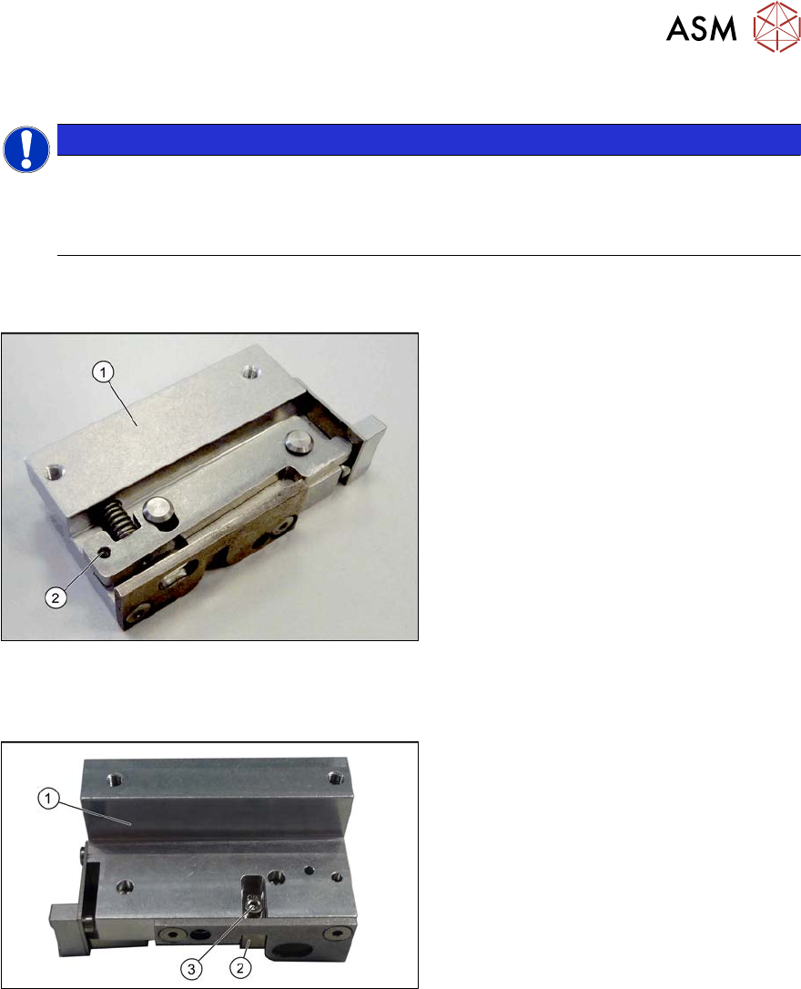
There are numerous versions of the clamping units. These differ, above all by the sensor flag:
Fig.302: Clamp version 1
Version 1
1. Clamp
2. An M3x16 mm screw can be inserted
here to permanently release the clamp.
► For details about replacing the clamping units (version 1), read section 7.5.10 "Replacing the
Clamping Unit (Version 1) (DC Only)" [}238].
Fig.303: Clamp version 2
Version 2
1. Clamp
2. Sensor switch
3. Fastening screw for sensor switch
► For details about replacing the clamping units (version 2), read section 7.5.11 "Replacing the
Clamping Unit (Version 2) (DC Only)" [}242].
7 Conveyor
7.5 Width Adjustment, Clamps and Cylinder Unit
238 Service Manual SIPLACE X-Serie S 06/2019
7.5.10 Replacing the Clamping Unit (Version 1) (DC Only)
Parts, equipment and tools
Select the clamping unit needed:
NOTICE
New clamping units only
Clamping units with version 1 are being replaced with new downwards compatible version 2
clamping units. Spare parts are now only available for version 2 clamping units (see follow-
ing table).
Side (DC) Input area and center Output area
A Clamping unit A1 SXa [03092996Sxx] Clamping unit A2 SXa [03092973Sxx]
B Clamping unit B1 SXa [03092453Sxx] Clamping unit B2 SXa [03092891Sxx]
C Clamping unit C1 SXa [03092901Sxx] Clamping unit C2 SXa [03092712Sxx]
D Clamping unit D1 SXa [03092989Sxx] Clamping unit D2 SXa [03092997Sxx]
●
1 feeler gauge [00094020-xx]
●
1 feeler gauge 0.3mm
●
Torque wrench (2–25Nm) [00376625‑xx]
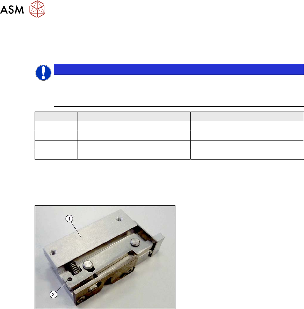
Overview
Fig.304: Clamp version 1
Version 1
1. Clamp
2. An M3x16 mm screw can be inserted
here to permanently release the clamp.
Version has no sensor flag.
7 Conveyor
7.5 Width Adjustment, Clamps and Cylinder Unit
Service Manual SIPLACE X-Serie S 06/2019 239
Removal
► Use the software to move the conveyor sides into a position which allows you best access.
The sides must move freely. Fix all 3 clamping units into place with one screw each, so that
the clamp is not able to exert any force onto the conveyor side.
7.2 "Loosening the Conveyor Side Clamps" [}207]
► Switch off the machine, disconnect it from the power supply and secure it to prevent
unauthorized reactivation.
1.2 "Preparatory work..." [}16]
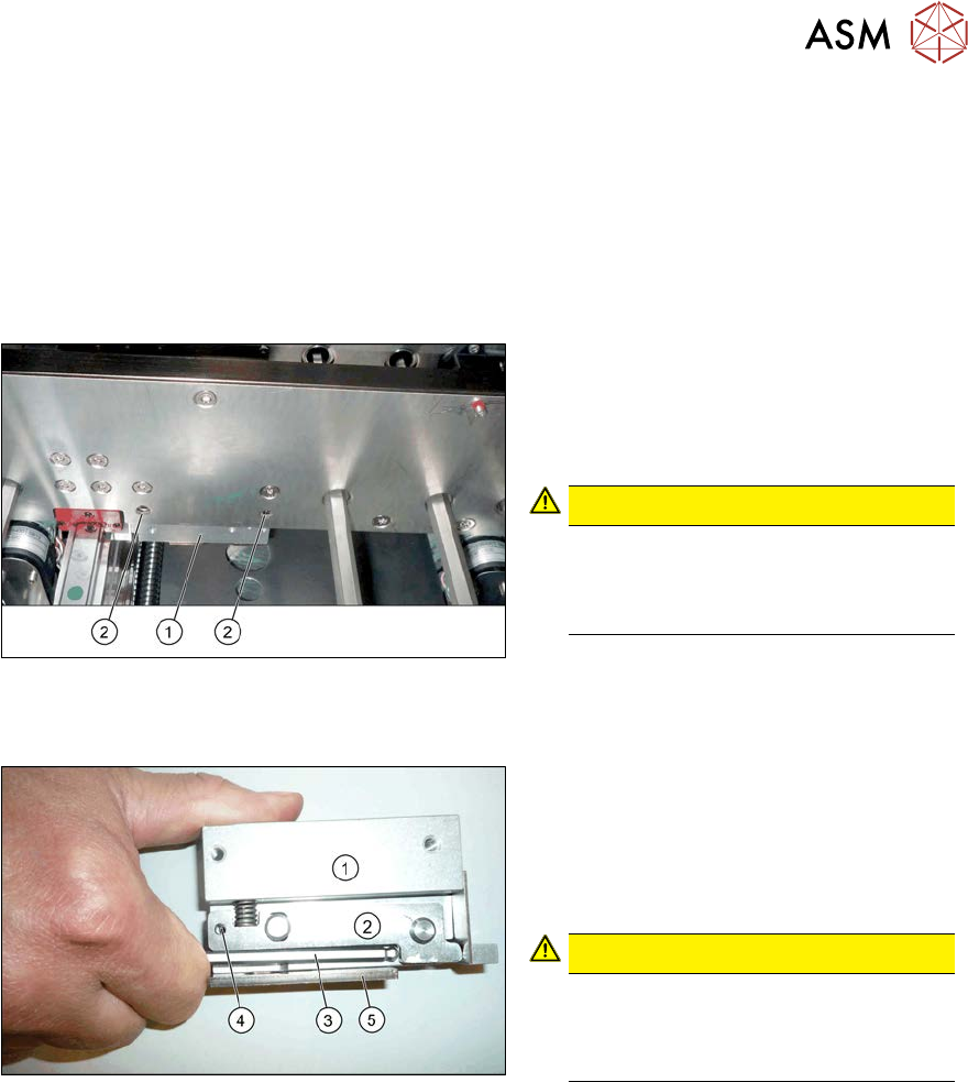
Fig.305: Removing the clamp
► Remove the two screws (2) fastening
the clamp(1). These are on the side of
the conveyor side which faces away
from the clamp. Make sure that you do
not loosen any other screws!
CAUTION!
The screws fastening the clamps may
only be loosened if the clamps have
already been fixed in place with a spe-
cial screw!
.
Installation
Fig.306: Fixing the clamping lever
► Use an M3 screw to fix the clamping
lever(2) to position(4) on the new
clamp(1), to achieve a defined position
for setting later on. To do this, press
the clamping lever up with an Allen
key(3).
CAUTION!
Make sure that you do not distort the
guide plate(5). If you do, this could
lead to problems with recognizing the
position of the conveyor side.
.
► Fit the clamp but only tighten the two fastening screws gently to begin with.
► Move the cylinder unit until it is under the clamps. To do this, move the toothed belt of the
width adjustment.