00197042-04_SM_X-Serie-S_Customer_EN.pdf - 第81页
3 Power supply 3.4 Power supply and transformer module (up to serial number Gxxx) Service Manual SIPLACE X-Serie S 06/2019 81 Fig.90: Fitting the axis support ► Gently insert the axis support and attach the switching ax…
3 Power supply
3.4 Power supply and transformer module (up to serial number Gxxx)
80 Service Manual SIPLACE X-Serie S 06/2019
► Unplug the electrical connections to the motor protection switch. You may want to mark the
positions of these connections to make clear assignment easier later on.
NOTICE
Orientation of the motor protection switch
In older machines, the motor protection switch is installed at an angle of 180°. In this case
the connectors 1 to T3 are located on top.
► Mark the position of the motor protection switch on the mounting rail.
► Lift the motor protection switch off the mounting rail.
Installation
► Remove the shunt release from the old motor protection switch and install it on the new one.
► Fit the new motor protection switch together with the shunt release on the mounting rail. Make
sure to position and align it correctly (observe the marking).
► Reestablish all electrical connections.
The clamping screws are fastened with a torque. The valid torque values are printed on the
packaging of the motor protection switch:
Flexible cable 1.5 - 4 mm² → 1.7 Nm
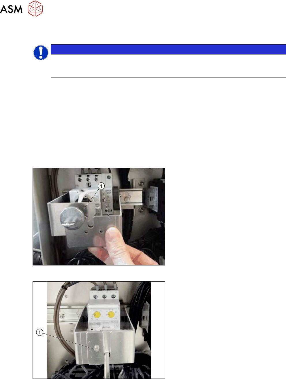
Fig.88: Shaft support, fitted (example of SX1)
► Fit the two shaft support plates(1) on
the mounting rail. Make sure that the
gray clamping blocks engage with the
mounting rail.
Fig.89: Shaft support, fitted (example of SX1)
► Secure the two shaft support plates
with the fastening screw(1).
3 Power supply
3.4 Power supply and transformer module (up to serial number Gxxx)
Service Manual SIPLACE X-Serie S 06/2019 81
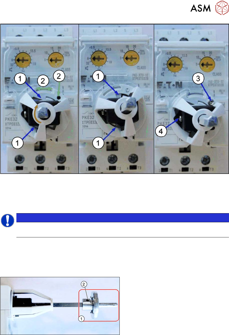
Fig.90: Fitting the axis support
► Gently insert the axis support and attach the switching axis (do not fix it yet).
Make sure that the two snap tabs of the axis support(1) can lock in place with the motor pro-
tection switch by slightly rotating the axis support (green arrow). The hole in the base of the
axis support(2) is now above a hole in the PKE switch.
NOTICE
The snap tabs break easily.
Proceed with caution as the snap tabs can break easily.
► Fix the axis support on the motor protection switch with the(3) screw supplied. Tighten the
screw with a torque of 0.5 to 1Nm. The screw is self-drilling.
► Adjust the position indicator on the axis. In the switched-off position, the arrow points to the
left if the setting screws of the PKZ are on top. Fix the position indicator with the screw(4).
Tighten the screw with a torque of 0.5 to 1Nm.
Fig.91: Fitting the switch bracket
► Fit the switch bracket(1) with the grub
screw(2). Tighten these with a torque
of 0.6Nm.
► Follow the removal instructions in reverse order for installation. Also observe the following
instructions:
– Set the nominal current and overcurrent (see below).
3 Power supply
3.4 Power supply and transformer module (up to serial number Gxxx)
82 Service Manual SIPLACE X-Serie S 06/2019
3.4.21.1 Adjustment of the Motor Protection Switch PKE32
This section applies only for the "motor protection switch PKE32" [03098183‑xx].
NOTICE
Supply of the vacuum pump with machine current
The following adjustment values are valid for all machines.
Exception: For machines with vacuum pumps that are supplied via the machine power sup-
ply other values may apply.
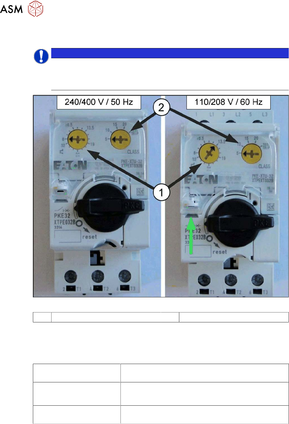
Fig.92: Adjusting the settings of the protective motor switch PKE32
1 Rated current 2 Overcurrent class
► At the marked position (green arrow), open the cover above the adjustment screws. Use a
size 1 screwdriver for this.
► Set the overcurrent class (2) to the value 5. This applies to all machines.
► Set the rated current (1) to the following values:
Without vacuum pump
●
240/400V 50Hz network: rated current: 8.0A
●
110/208V 60Hz USA network: rated current: 13.5A
With one vacuum pump
(SX1/SX2, DX1/DX2, SX4/DX4,
X-Series S)
●
240/400V (50Hz) network: rated current: 8.0A
●
110/208V (60Hz ) USA network: rated current: 13.5A
With two vacuum pumps
(SX4/DX4, X-Series S)
●
240/400V (50Hz) network: rated current: 13.5A
●
110/208V (60Hz ) USA network: rated current: 17.2A