00197042-04_SM_X-Serie-S_Customer_EN.pdf - 第335页
9 Component feeding 9.1 Cutter Service Manual SIPLACE X-Serie S 06/2019 335 9.1.6 Replacing the protective plate Parts Fig.432: Protective plate 03019894‑xx Protective plate Equipment and tools 00353832-xx Allen key set…
9 Component feeding
9.1 Cutter
334 Service Manual SIPLACE X-Serie S 06/2019
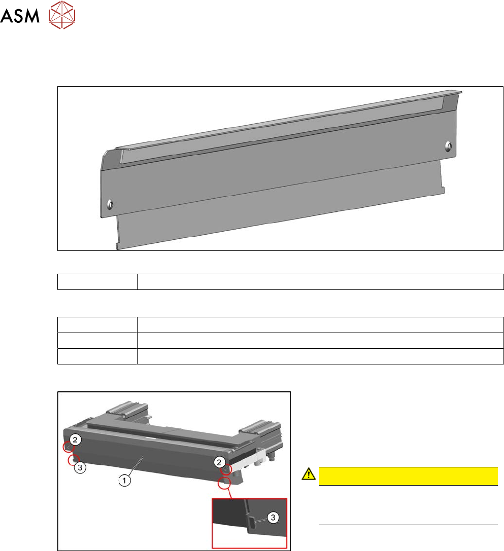
9.1.5 Replacing the baffle plate
Parts
Fig.430: Baffle plate
03019896‑xx Baffle plate
Equipment and tools
00353832-xx Allen key set
Wire cutters
Cable ties
Overview
Fig.431: Cutter
1. Baffle plate [03019896-xx]
2. Two fastening screws
3. Clip connecting baffle plate and pro-
tective plate
CAUTION!
Risk of injury
There is a risk of injuring yourself on
the cutting edge of the blades.
.
Removal
► Switch off the machine, disconnect it from the power supply and secure it to prevent
unauthorized reactivation.
1.2 "Preparatory work..." [}16]
► Remove the cutter from the machine.
9.1.3 "Replacing the Cutter on the COT Insert [03066690-xx]" [}329]
► Straighten the two clips with pliers.
► Remove the two screws fastening the baffle plate.
► Remove the baffle plate unit from the cutter.
Installation
► Follow the removal instructions in reverse order for installation.
9 Component feeding
9.1 Cutter
Service Manual SIPLACE X-Serie S 06/2019 335
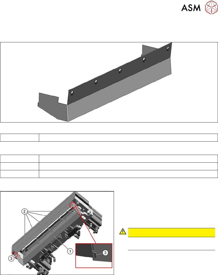
9.1.6 Replacing the protective plate
Parts
Fig.432: Protective plate
03019894‑xx Protective plate
Equipment and tools
00353832-xx Allen key set
Wire cutters
Cable ties
Overview
Fig.433: Protective plate on cutter
1. Protective plate [03019894-xx]
2. Five fastening screws
3. Clip connecting baffle plate and pro-
tective plate
CAUTION!
There is a risk of injuring yourself on
the cutting edge of the blades.
.
Removal
► Switch off the machine, disconnect it from the power supply and secure it to prevent
unauthorized reactivation.
1.2 "Preparatory work..." [}16]
► Remove the cutter from the machine.
9.1.3 "Replacing the Cutter on the COT Insert [03066690-xx]" [}329]
► Remove the five screws fastening the protective plate.
► Straighten the two clips with pliers.
► Remove the protective plate from the cutter.
9 Component feeding
9.1 Cutter
336 Service Manual SIPLACE X-Serie S 06/2019
Installation
► Follow the removal instructions in reverse order for installation. Also observe the following
instructions:
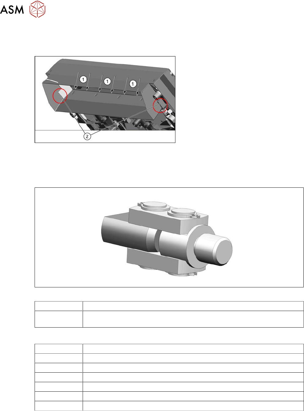
Fig.434: Fitting the protective plate
► Make sure that the five fastening
screws are completely countersunk.
The screws must be flush with the pro-
tective plate.
► Ensure that there is a gap between the
cutter blade and the edge of the baffle
plate inside(1).
► If everything is correct, there should be
a contact at position(2).
9.1.7 Replacing the articulated joint on the short-stroke cylinder
Parts
Fig.435: Joint
03000518-xx Articulated joint on the short-stroke cylinder
03057290-xx 2x hexagon socket fillister head screws ISO4762-M5x35-12.9, geomet. 321+VL
(screws for movable blade)
Equipment and tools
00376625‑xx Torque wrench 2.5‑25Nm
03121952-xx Lubrication grease BEM 34-132, 400 g cartridge
03123777-xx One-hand grease gun for 400 ml cartridge
00334892‑xx Loctite 243
00353832-xx Allen key set
Wire cutters
Cable ties