00197042-04_SM_X-Serie-S_Customer_EN.pdf - 第77页
3 Power supply 3.4 Power supply and transformer module (up to serial number Gxxx) Service Manual SIPLACE X-Serie S 06/2019 77 Installation Motor protection trip block settings Motor protec- tion trip block Yellow setting…
3 Power supply
3.4 Power supply and transformer module (up to serial number Gxxx)
76 Service Manual SIPLACE X-Serie S 06/2019
Removal
► Switch off the machine, disconnect it from the power supply and secure it to prevent
unauthorized reactivation.
1.2 "Preparatory work..." [}16]
► Before you start working, check the power supply for absence of voltage and observe the
waiting times!
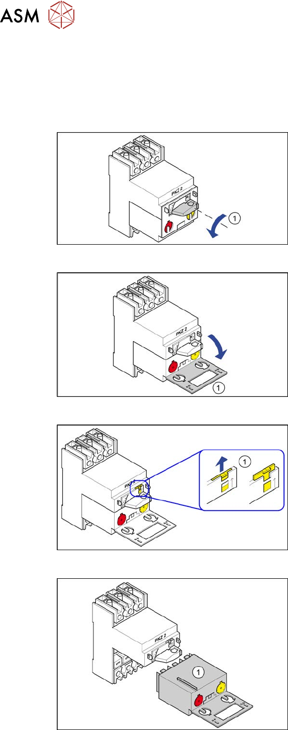
Fig.78: Position "0"
► Turn the switch(1) anticlockwise to the
position"0"
Fig.79: Swing open
► Open the protective flap(1).
Fig.80: Locking tab
► Use a screwdriver to push the yellow
locking tab(1) upwards.
Fig.81: Motor protection trip block
► Pull the motor protection trip block(1)
out.
3 Power supply
3.4 Power supply and transformer module (up to serial number Gxxx)
Service Manual SIPLACE X-Serie S 06/2019 77
Installation
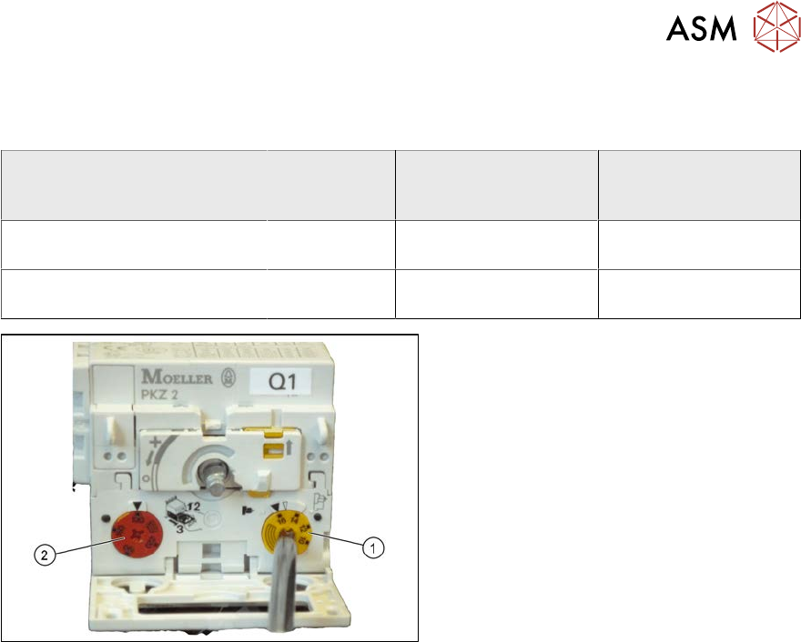
Motor protection trip block settings
Motor protec-
tion trip
block
Yellow setting disk
for overcurrent trig-
ger threshold
Red setting disk for
short-circuit current
trigger threshold
X-Series/SX4/DX4 for 3x208V~
+/‑5% (USversion)
ZM-32-PKZ2 24 A 375 A
X-Series/SX4/DX4 for 3x400V~
+/‑5%
ZM-16-PKZ2 16 A 200 A
Fig.82: Motor protection trip block – settings
► Check the trigger threshold for overcur-
rent (yellow setting disk(1)).
► Check the trigger threshold for short-
circuit current (red setting disk(2)).
► Insert the motor protection trip block.
► Push the yellow locking tab down-
wards.
► Close the gray protective flap.
► Turn the rotary switch clockwise as far
as the stop.
3 Power supply
3.4 Power supply and transformer module (up to serial number Gxxx)
78 Service Manual SIPLACE X-Serie S 06/2019
3.4.21 Replacing the motor protection switch PKE32/XTU-32
CAUTION
New version
Do not confuse this version of the motor protection switch with the old one. Pay particular
attention to the settings.
NOTICE
Missing axis support
The machine is switched on with the help of an extension axis via the protective motor
switch. When inserting the door coupling handle onto the extension axis of the protective
motor switch, the axis could move into a slanted position. In this case, high traverse forces
will be exerted against the axis coupling of the protective motor switch, which could then
break. This would then make it impossible to switch the machine on or off.
Some machines do not have this additional axis support on the protective motor switch.
This support is used to limit the slant of the extension axis and therefore to reduce the tra-
verse forces against the axis coupling.
► This axis support can be retrofitted. For details, read the Technical Information "Retro-
fit Guide Axis Support Motor Circuit Breaker PKE32/XTU-32 Assembly 3p. (Main
Switch)" [DE: TI2013-07D10] [EN: TI2013-07E10].
Parts, equipment and tools
●
Motor protection switch PKE32/XTU-32 assembly 3p. [03098183-xx]
The motor protection switch is supplied together with the protection trip block.
●
Technical information "Retrofit Guide Axis Support Motor Circuit Breaker PKE32/XTU-32
Assembly 3p. (Main Switch)" [DE: TI2013-07D10] [EN: TI2013-07E10].
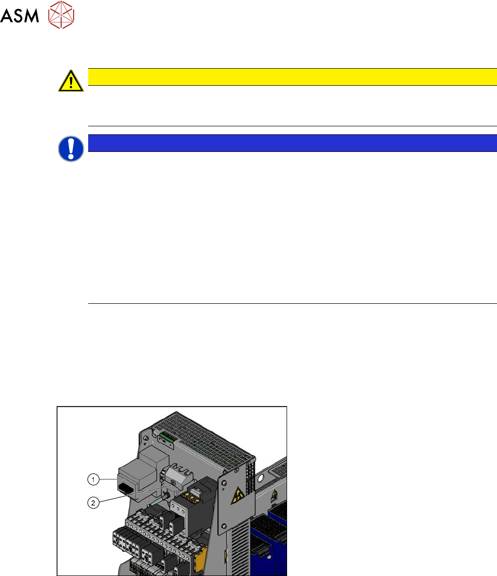
Overview
Fig.83: Motor protection switch and main switch (using
example of US version for the X-Series)
1. Motor protection switch
2. Main switch (US version only)
In non-US versions, the motor protection
switch also serves as the main switch.
Removal
► Switch off the machine, disconnect it from the power supply and secure it to prevent
unauthorized reactivation.
1.2 "Preparatory work..." [}16]
► Before you start working, check the power supply for absence of voltage and observe the
waiting times!