00197042-04_SM_X-Serie-S_Customer_EN.pdf - 第196页
6 Gantries 6.6 HCU, MHCU, boards and camera 196 Service Manual SIPLACE X-Serie S 06/2019 6.6.4 Replacing the connection cable from the Twin module to the HCU basic adapter Parts, equipment and tools ● Cable / X connectio…
6 Gantries
6.6 HCU, MHCU, boards and camera
Service Manual SIPLACE X-Serie S 06/2019 195
6.6.3 X Base adapter Twin
This board is used for Twin heads on SIPLACE X-Series S, SX4/DX4, TX and TX V2-Series ma-
chines.
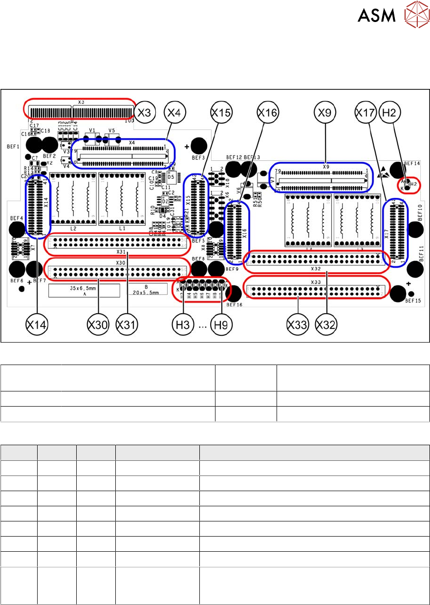
Fig.246: X base adapter Twin [03062201-03]
X4 X14 X15 Connection for MHCU (Twin mod-
ule2)
X9 X16 X17 Connection for MHCU (Twin mod-
ule1)
X30 X31 Connections for Twin module 2 X32 X33 Connections for Twin module 1
X3 Connection on the head interface H2 to H9 LEDs (see below)
LED [03054879-03]
LED Color Status Signal name Description
H2 GN ON - HMCU2 programming connector connected
H3 RD ON FPGA_TEST_6 1.5VDC PowerFail
H4 RD ON FPGA_TEST_2 3.3VDC PowerFail
H5 RD ON FPGA_TEST_4 5VDC PowerFail
H6 RD ON FPGA_TEST_1 15VDC PowerFail
H7 RD ON FPGA_TEST_3 DP PowerFail, not used
H8 RD ON FPGA_TEST_5 24VDC PowerFail
H9 RD ON POWER-
FAIL_LOCAL
PowerFail board:
ON, when 1.5VDC, 3.3VDC, 5VDC and 15VDC are
outside the permissible tolerance
The voltage monitors trigger as soon as the target voltage is undershot by 5%.
6 Gantries
6.6 HCU, MHCU, boards and camera
196 Service Manual SIPLACE X-Serie S 06/2019
6.6.4 Replacing the connection cable from the Twin module to the HCU basic
adapter
Parts, equipment and tools
●
Cable / X connection cable Twin [03062202-xx]
Overview
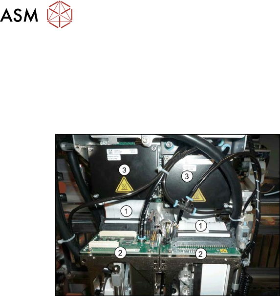
Fig.247: Cables
1. Connection cable from the Twin mod-
ule to the HCU basic adapter
2. Twin module
3. HCUs on the HCU base adapter
Removal
► Switch off the machine, disconnect it from the power supply and secure it to prevent
unauthorized reactivation. Observe the instructions in section 1.2 "Preparatory work..." [}16].
► Remove the two Twin modules form the machine (see 8.7 "Replacing the SIPLACE
Twin" [}320]).
► Remove the head adapter HCU from the machine and then dismantle the two HCUs. (see
6.6.1 "Replacing the MHCU, basic and head adapter" [}191]).
► Unplug both connection cables.
Installation
► Follow the removal instructions in reverse order for installation.
6.6.5 Replacing the PCB Camera
Parts, equipment and tools
●
SIPLACE X-Series S up to Gxxxx: PCB camera (type 34) 28 digital RK [03075363‑xx]
●
SIPLACE X-Series S from Hxxxx: PCB camera (type 34) 28 GigE [03101402‑xx]
●
Sealing varnish Loctite 241 [02101037-xx]
6 Gantries
6.6 HCU, MHCU, boards and camera
Service Manual SIPLACE X-Serie S 06/2019 197
Overview
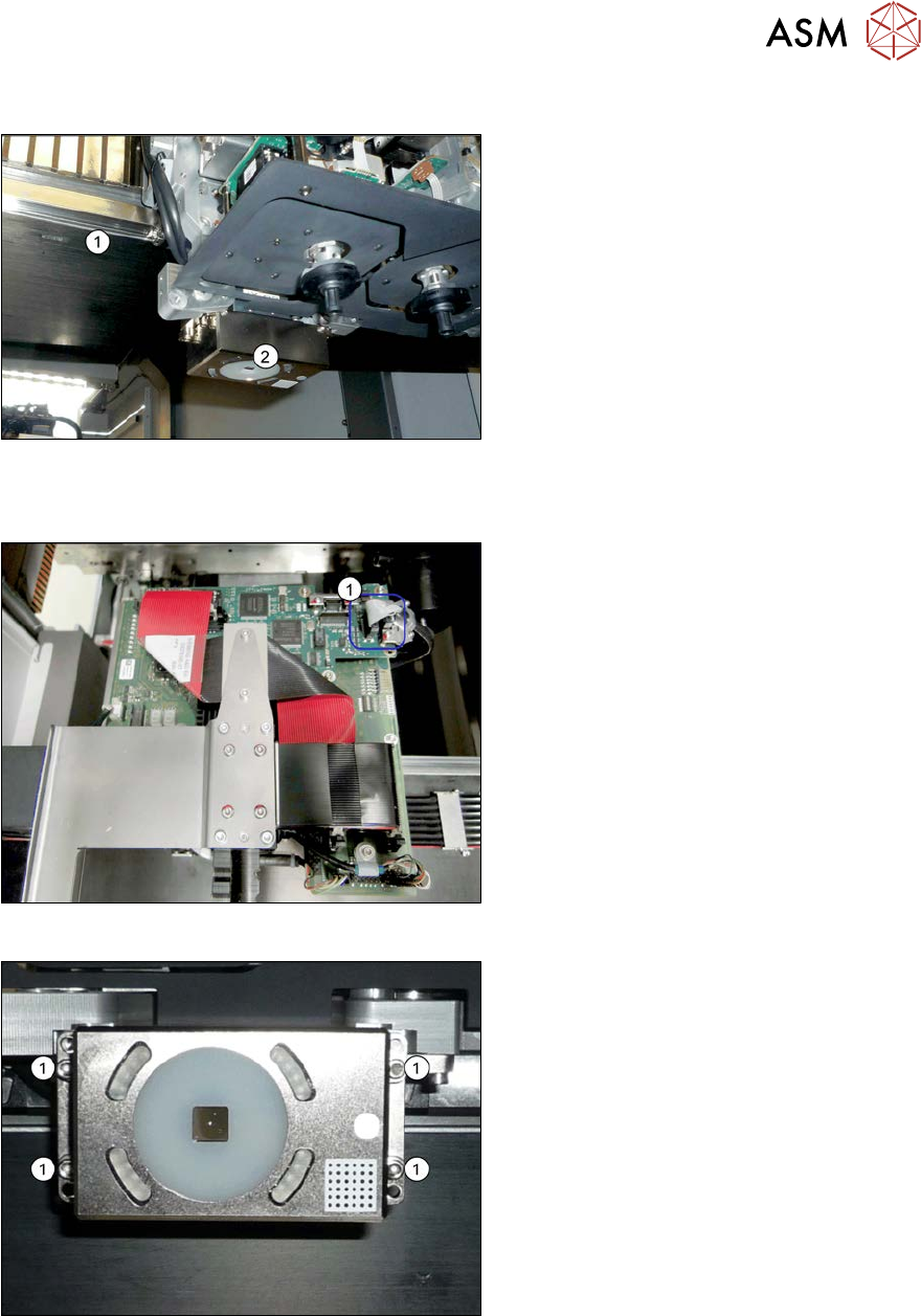
Fig.248: Overview of PCB camera
1. Gantry
2. PCB camera
The PCB camera is located on the under-
side of the gantry, on the head mount.
Removal
Fig.249: Connecting cable
► Unplug the two connection cables X2
and X6(1) from the Vision board and
unthread as far as the PCB camera.
You may like to mark their positions, to
make clear assignment easier later on.
Fig.250: PCB camera
► Remove the four screws (1) holding the
PCB camera. Mark the position to
make clear assignment easier later on.
Installation
► Install the new PCB camera on the mount. Secure the screws with Loctite 241.
► Run the connection cable to the Vision board and reconnect to the electrical system.
► After replacing the PCB camera, you will need to recalibrate the whole machine. Use the rel-
evant software function in the Service menu.