00197042-04_SM_X-Serie-S_Customer_EN.pdf - 第371页
9 Component feeding 9.2 COT insert Service Manual SIPLACE X-Serie S 06/2019 371 9.2.11 Replacing the infeed control Parts, equipment and tools Fig.496: Feed control 1. Infeed control assembly SX4 [03082077-xx] Removal ►…
9 Component feeding
9.2 COT insert
370 Service Manual SIPLACE X-Serie S 06/2019
Removal
CAUTION
Do not dismantle the empty tape duct
Only the empty tae duct Einsatz may be replaced. Dismantling the empty tape duct is not
permitted.
NOTICE
Inner empty tape duct Einsatz
When using tape reels with deep pockets, you may need to remove the inner baffle. Refer
to the operating manual of your machine for details.
All screws are accessible in the installed state. The baffles can therefore be replaced inside
the machine.
► Remove the two screws fastening the empty tape duct Einsatz and remove these.
Installation
► Installation is performed by following the above instructions in the reverse order. Also observe
the following instructions:
– Refit the empty tape duct Einsatz on the empty tape duct if you are not using any compon-
ents >15mm.
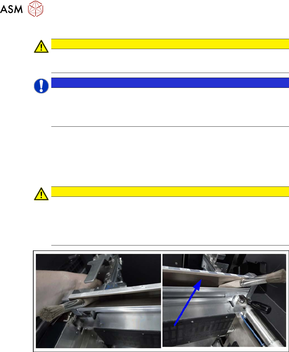
CAUTION
The empty tape duct Einsatz fits somewhat tightly in the empty tape duct
These can damage the coating in the empty tape duct, which can then lead to component
tapes getting jammed at the edges. This could then cause a head crash.
► Never use sharp-edged objects to position the empty tape duct Einsatz.
► If necessary, use a wooden wedge or, as shown in the following diagram, a brush with
wooden handle.
Fig.495: Empty tape duct
9 Component feeding
9.2 COT insert
Service Manual SIPLACE X-Serie S 06/2019 371
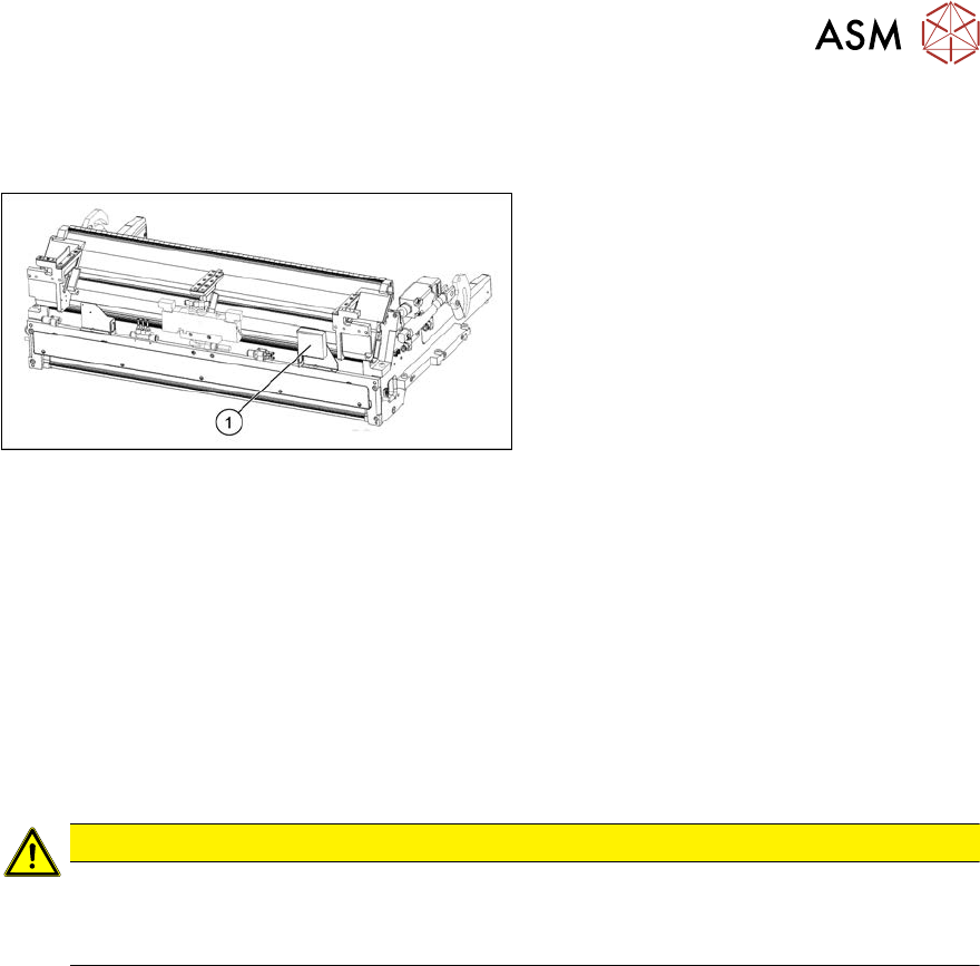
9.2.11 Replacing the infeed control
Parts, equipment and tools
Fig.496: Feed control
1. Infeed control assembly SX4
[03082077-xx]
Removal
► Switch off the machine and secure it to prevent unauthorized reactivation. Observe the
instructions in section 1.2 "Preparatory work..." [}16].
► Dismantle the nozzle changer over the infeed control (see 2.8.2 "Replacing the Nozzle
Changer" [}44]).
► To gain better access, you may need to disconnect the COT insert and pull it slightly out of
the machine. Observe the instructions in section 9.2.2 "Installation Positions of COT Insert and
Manual Table (Table Positions)" [}356].
Alternatively, you can improve access by removing the upper section of the component cam-
era.
CAUTION
Component camera
► The component camera mirror has sharp edges.
► Take care not to damage the component camera.
► Unplug all electrical connections to the insert control. You may want to mark their positions, to
make clear assignment easier later on.
► Remove the screws fastening the infeed control and remove the insert control from the
machine.
Installation
► Follow the removal instructions in reverse order for installation.
9 Component feeding
9.3 X-Series Component Trolley
372 Service Manual SIPLACE X-Serie S 06/2019
9.3 X-Series Component Trolley
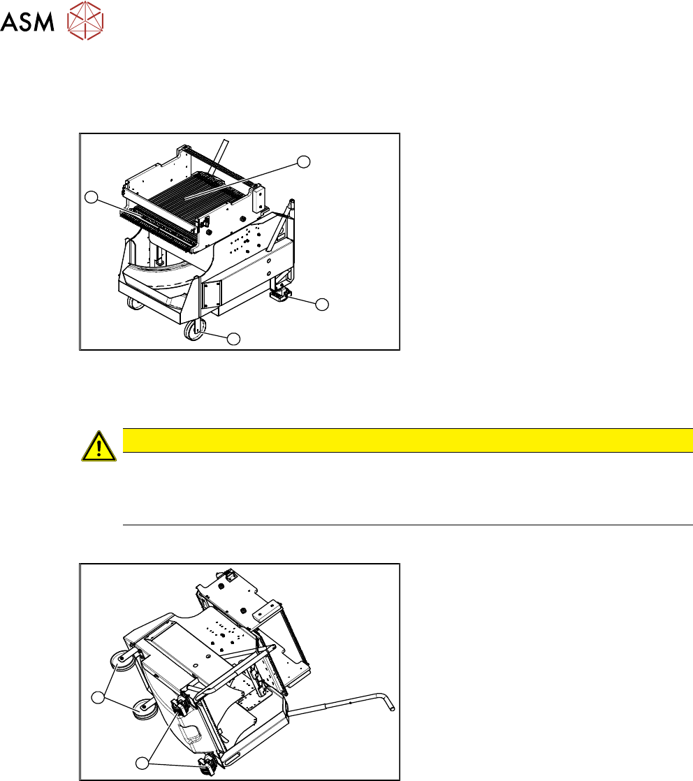
9.3.1 SIPLACE X-series component trolley
1
4
3
2
Fig.497: SIPLACE X-series component trolley
1. Guide castor
2. Fixed castor
3. Locking strip
4. Support block
9.3.2 Replacing the Fixed/Guide Castors [00341918-xx]
CAUTION
Heavy machine part!
The component trolley must be placed on one side in order to remove the fixed/guide
castors. The component changeover table is extremely heavy! You will need two people to
perform this task.
Parts, equipment and tools
1
2
Fig.498: Fixed and guide castors (example of SIPLACE
X‑Series shown)
1. Fixed castor [00341918-xx]
2. Guide castor [03004958-xx]
●
Second person
Removal/Installation
► Remove all feeders from the component trolley.
► Move the component trolley out of the machine.
► Place the component trolley down on its side, on a suitable surface.
► Undo the screws fastening the fixed/guide castor to to replaced and then remove the castor.
► Insert the new fixed/guide castor.
► Stand the component trolley on its wheels again.