00197042-04_SM_X-Serie-S_Customer_EN.pdf - 第29页
2 Basic Machine 2.3 Guide Rollers on the Covers Service Manual SIPLACE X-Serie S 06/2019 29 2.3 Guide Rollers on the Covers NOTICE Example shown as diagram The following sections are described using the example of an SX1…
2 Basic Machine
2.2 Replacing the gas pressure shock absorber on the cover
28 Service Manual SIPLACE X-Serie S 06/2019
2.2.1 Troubleshooting – Loose Screwed Fixtures on the Gas Pressure Shock
Absorbers
Problem
Due to loosened screwed fixtures on the gas pressure shock absorbers, there is a risk of a gantry
crash.
Cause
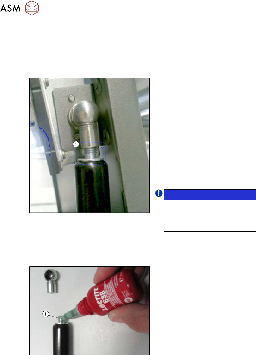
Fig.12: Screwed fixture
In older gas pressure shock absorber ver-
sions with FS01, the screwed fixtures(1)
between the gas pressure shock absorber
and the end pieces could loosen.
SX1/SX2/DX1/DX2:
Gas pressure shock absorbers 08/19 175N
[03057763‑01]
SIPLACE SX4/DX4/X-Series S:
Gas pressure shock absorbers
D3D3B90-135-430-004/230N [03086743‑01]
Machines affected:
SX1/SX2, DX1/DX2: K001G- to K800G-,
L001G- to L059G-, L200G- to L499G-
SX4/DX4: F001- to F186-
X-Series S: G001- to G102-
NOTICE!
This problem no longer exists in ma-
chines manufactured since week
30/2013 or in newer versions of the
gas pressure shock absorbers with
FS02.
.
Parts, equipment and tools
●
Loctite 638 [00317731-xx], if required
Troubleshooting for FS01
Fig.13: Fix the screws with adhesive
► Check the screwed fixtures on the gas
pressure shock absorbers.
► If the screwed fixtures have loosened,
proceed as follows:
► Remove the gas pressure shock ab-
sorber (see previous chapter).
► Dismantle the two end pieces.
► Make sure that the thread is free of
grease and dust.
► Coat the thread of the gas pressure
shock absorber with Loctite 638 and
then screw the end pieces back onto
the gas pressure shock absorber.
► Fit the gas pressure shock absorber
again (see previous chapter).
2 Basic Machine
2.3 Guide Rollers on the Covers
Service Manual SIPLACE X-Serie S 06/2019 29
2.3 Guide Rollers on the Covers
NOTICE
Example shown as diagram
The following sections are described using the example of an SX1/SX2 machine. The pro-
cedure is the same for other machines. Any relevant differences will be mentioned expli-
citly.
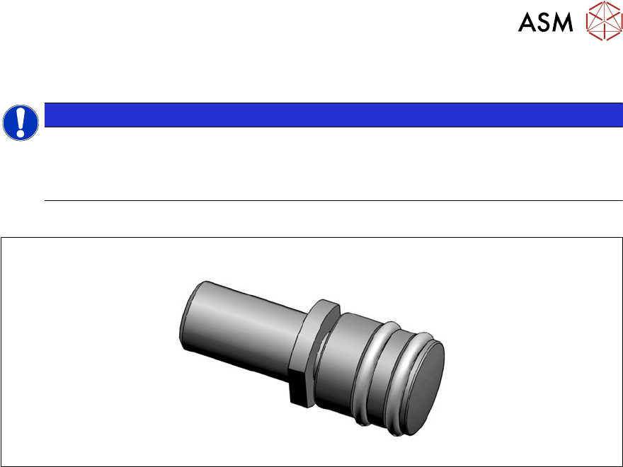
Parts, equipment and tools
Fig.14: Guide roller [03078561-xx]
●
Per machine:
– 8x roller assy – 1 unit [03078561-xx]
– 8x DIN EN ISO 4028 M8x16-A2-21H – pack of 10 [03027433‑xx] (replaces[00304354‑xx])
or
8x DIN EN ISO4026-M8x16-A2-21H - pack of 10 [03025582-xx]
●
Fork wrench, size 10
●
Allen key
2 Basic Machine
2.3 Guide Rollers on the Covers
30 Service Manual SIPLACE X-Serie S 06/2019
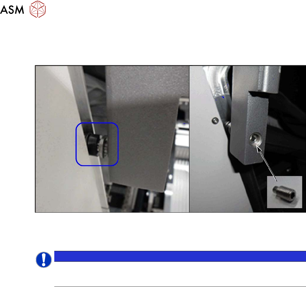
Procedure
► To make the work easier, proceed as follows:
Dismantle the bottom stop.
► Loosen the screwed fixture on the roller (fork wrench size10). Unscrew as far as required.
Fig.15: Threaded pin
► From the inside, screw on a threaded pin as lock and tighten it.
Checks
NOTICE
Covering
Between the roller and the guidance there must be at least 75% coverage along the entire
length of the guide rails.
► Check whether the cover can be easily moved along the whole area. Adjust the cover if ne-
cessary (see 2.4 "Setting the Covers" [}31]).