00197042-04_SM_X-Serie-S_Customer_EN.pdf - 第74页
3 Power supply 3.4 Power supply and transformer module (up to serial number Gxxx) 74 Service Manual SIPLACE X-Serie S 06/2019 Removal ► Switch off the machine, disconnect it from the power supply and secure it to prevent…

3 Power supply
3.4 Power supply and transformer module (up to serial number Gxxx)
Service Manual SIPLACE X-Serie S 06/2019 73
3.4.19 Replacing the motor protection switch PKZ2
NOTICE
Old version [00342494-xx]
This version of the motor protection switch has been discontinued and may need to be re-
placed with the new version "motor protection switch PKE32/XTU-32 assembly 3-
pin" [03098183-xx].
► Read also section 3.4.21 "Replacing the motor protection switch PKE32/
XTU-32" [}78] and the technical information "Product discontinuation of "motor pro-
tection switch PKZ2 basic machine, 3-pin" [00342494-xx]" [TI2015-03D02] [EN:
TI2015-03E02].
NOTICE
Motor protection trip block
The corresponding motor protection trip block belongs to the motor protection switch.
► For details about replacing the motor protection trip block, refer to section 3.4.20 "Re-
placing the Motor Protection Release Block (PKZ2)" [}75]. Pay particular attention to
the correct settings.
Parts, equipment and tools
●
Motor protection switch PKZ2, basic device 3 pin [00342494-xx]
A motor protection trip block belongs to this:
– Motor protection trip block ZM-32-PKZ2 (US version) [00342496-xx]
– Motor protection trip block ZM-16-PKZ2 (all except US) [00342495-xx]
Overview
Fig.74: Motor protection switch and main switch (using
example of US version for the X-Series)
1. Motor protection switch
2. Main switch (US version only)
In non-US versions, the motor protection
switch also serves as the main switch.
3 Power supply
3.4 Power supply and transformer module (up to serial number Gxxx)
74 Service Manual SIPLACE X-Serie S 06/2019
Removal
► Switch off the machine, disconnect it from the power supply and secure it to prevent
unauthorized reactivation.
1.2 "Preparatory work..." [}16]
► Before you start working, check the power supply for absence of voltage and observe the
waiting times!
► Unplug all connections to the motor protection switch. You might like to mark their positions to
make clear assignment easier later on.
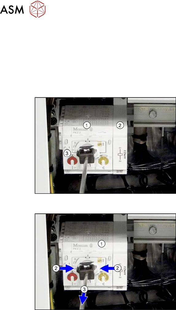
Fig.75: Motor protection switch
1. Motor protection switch PKZ2 basic
device 3 pin [00342494-xx]
(discontinued, not backwards compat-
ible)
2. Motor protection trip block A-PKZ2-A
[03078388-xx]
(discontinued, not backwards compat-
ible)
3. Motor protection trip block ZM-16-PKZ2
[00342495-xx]
or
Motor protection trip block ZM-32-PKZ2
[00342496-xx]
(discontinued, not backwards compat-
ible)
Fig.76: Dismantling the rod
► Remove the rod which connects the
motor protection switch(1) to the outer
main switch handle. To do this, press
the white plastic clips together(2) and
pull off the rod(3).
► Take the motor protection switch off the
rail.
Installation
► Follow the removal instructions in reverse order for installation. Also observe the following
instructions:
– Check the setting of the motor protection trip block (see 3.4.20 "Replacing the Motor Pro-
tection Release Block (PKZ2)" [}75]).
3 Power supply
3.4 Power supply and transformer module (up to serial number Gxxx)
Service Manual SIPLACE X-Serie S 06/2019 75
3.4.20 Replacing the Motor Protection Release Block (PKZ2)
NOTICE
Old version [00342494-xx]
This version of the motor protection switch has been discontinued and may need to be re-
placed with the new version "motor protection switch PKE32/XTU-32 assembly 3-
pin" [03098183-xx].
► Read also section 3.4.21 "Replacing the motor protection switch PKE32/
XTU-32" [}78] and the technical information "Product discontinuation of "Motor cir-
cuit breaker PKZ2 basic machine, 3-pin" [00342494-xx]" [TI2015-03D02] [EN:
TI2015-03E02].
Parts, equipment and tools
If you have supply voltages of 3x208 V~ and 3x230 V~, you will need to use the motor protection
trip block ZM-32-PKZ2 [00342496-xx].
●
Motor protection trip block ZM-16-PKZ2 [00342495-xx] (default)
●
Motor protection trip block ZM-32-PKZ2 [00342496-xx] (US version)
Overview
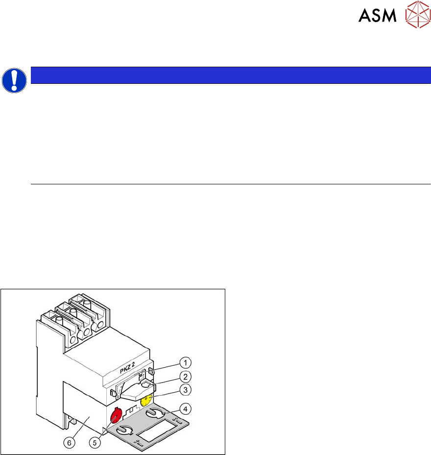
Fig.77: Motor protection switch
1. Locking tab
2. Rotary switch
3. Trigger threshold for overcurrent
(yellow setting disk)
4. Protective flap
5. Trigger threshold for short-circuit
current (red setting disk)
6. Motor protection trip block