00197042-04_SM_X-Serie-S_Customer_EN.pdf - 第149页
6 Gantries 6.3 X and Y axis Service Manual SIPLACE X-Serie S 06/2019 149 Overview Fig.184: Overview of incremental encoder 1. Incremental encoder (mounted on the holder) 2. Holder 3. Fastening screws (3x) for holder Fig…
6 Gantries
6.3 X and Y axis
148 Service Manual SIPLACE X-Serie S 06/2019
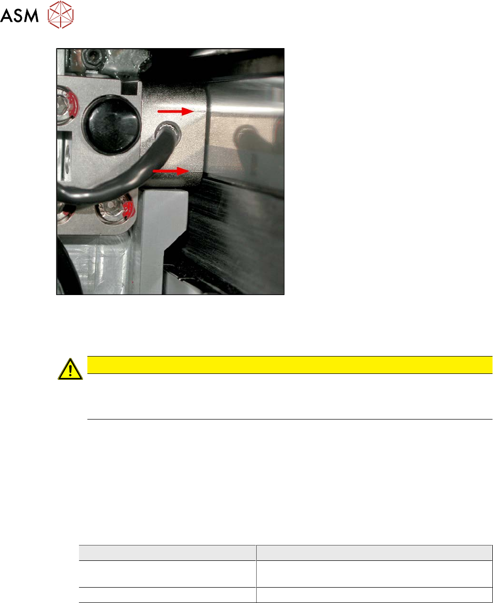
Fig.183: Casting marks on the incremental encoder
► Align the incremental encoder. Pay at-
tention to the following points:
– Set the exact height of the scale.
– Align the incremental encoder, us-
ing the two casting marks (arrows),
which mark the read area.
– Align the incremental encoder paral-
lel to the scale. The gap at the top
and bottom must be the same size.
► Tighten the fastening screws.
► Reconnect to the electricity supply (connector X14 or X15 on head interface).
CAUTION
Check how the cables are run!
► Make sure that the axes can be moved without damaging the cables.
► Fasten the cables with cable ties.
► Move the gantry into the end stopper and check that the buffer does not come into contact
with the cable.
► Check the track signals with the test device (see 6.3.8 "Track Signals and Zero
Pulse" [}153]).
6.3.2 Replacing the Y axis incremental encoder
Parts, equipment and tools
●
Select the correct incremental encoder:
Machine Incremental encoder (read head)
SIPLACE X4i S, X4 S, X3 S, X2 S MS22/25 Y axis [03094996‑xx] (including plastic
thickness gauge)
SIPLACE X4i S micron, X4 S micron MS30 Y axis [03102065‑xx]
●
If needed, mounting bracket for Y axis sensor [03086842-xx]
●
For MS22/25 incremental encoder: test device PG1-I [03102699‑xx]
●
For MS20/30/35 incremental encoder: test device PG-U [03071361‑xx] from FS02 (see also
technical information "Checking the track signals at the X and Y axes" [DE:TI2019‑02D04]
[EN:TI2019‑02E04])
●
Ethanol
Isopropanol – IPA can be used as an alternative.
6 Gantries
6.3 X and Y axis
Service Manual SIPLACE X-Serie S 06/2019 149
Overview
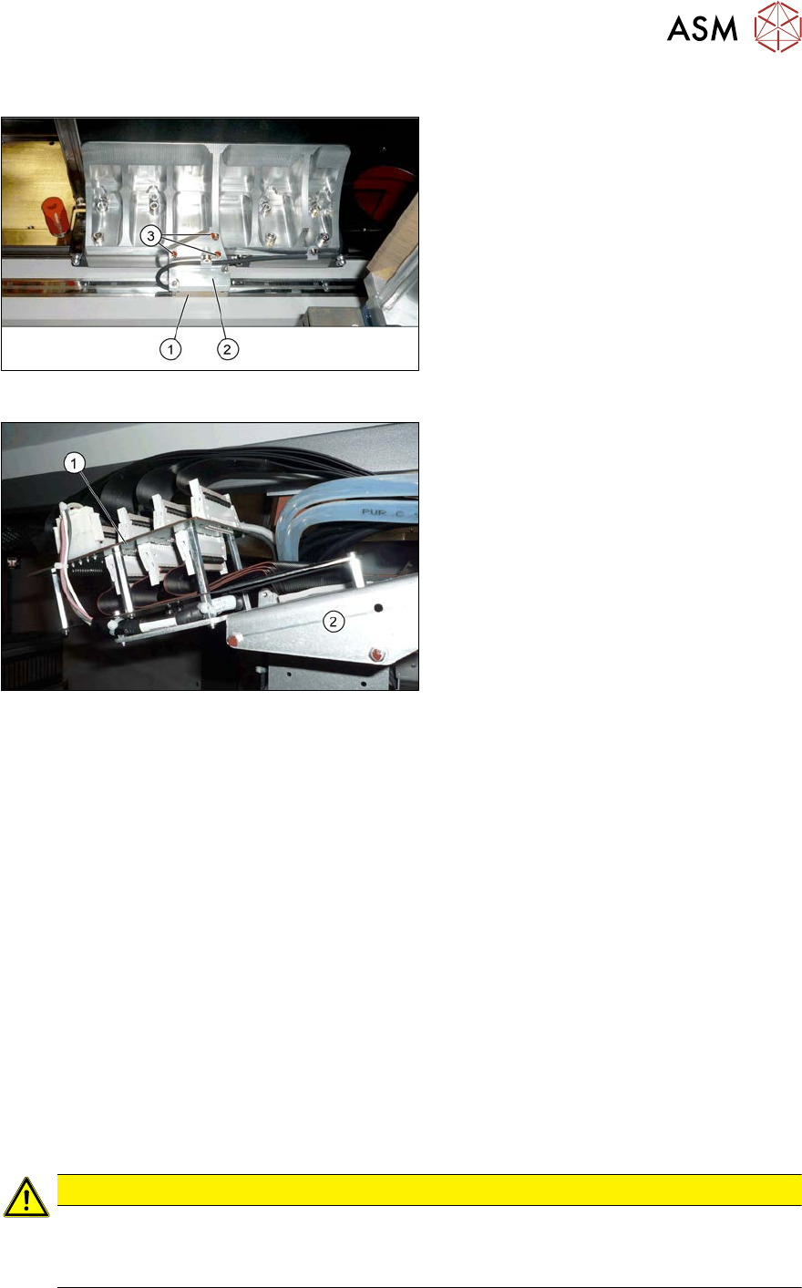
Fig.184: Overview of incremental encoder
1. Incremental encoder (mounted on the
holder)
2. Holder
3. Fastening screws (3x) for holder
Fig.185: Overview of gantry interface
1. Gantry interface
2. Trailing cable holder on gantry
Removal
► Switch off the machine, disconnect it from the power supply and secure it to prevent
unauthorized reactivation.
1.2 "Preparatory work..." [}16]
► Unplug the incremental encoder cable from the gantry interface. In this case make a note of
the position to make clear assignment easier later on.
► Unthread the connection cable as far as the incremental encoder.
► Remove the three screws fastening the incremental encoder holder and carefully remove this
together with the incremental encoder.
Installation
► Clean the reading surface of the incremental encoder with a cloth and ethanol or with a Q tip.
► Fit the incremental encoder with the three fastening screws. To do this, place the thickness
gauge provided between the incremental encoder and the scale, so that there is a gap. This
gap must either be 0.4mm (golden scale) or 0.75mm (black-white). Use the corresponding
thickness gauge (plastic).
► Reconnect to the electricity supply.
CAUTION
Make sure that the cables do not rub against anything.
Make sure that the axes can be moved without damaging the cables.
► Fasten them with cable ties
► Check the track signals with the test device (see 6.3.8 "Track Signals and Zero
Pulse" [}153]).
6 Gantries
6.3 X and Y axis
150 Service Manual SIPLACE X-Serie S 06/2019
6.3.3 Mechanical adjustment of the incremental encoder
The incremental encoders (read units) on the X and Y axis are adjusted exactly to the position of
the incremental scale. The two limit marks on the incremental encoder show where the top/bottom
positions of the scale should be.
Set the incremental encoder mechanically to a distance of 0.75 mm to the incremental encoder.
NOTICE
Plastic disks
To set this distance, use one or more small plastic disks with a total thickness of 0.75mm.
► Feeler gauge 0.75mm plastic [03090774-xx]
After this adjustment of the incremental encoder you have to check the zero pulse and track sig-
nals.
Correct installation should ensure correct count and zero pulse signals. For troubleshooting pur-
poses (error analysis and fixing), you will need to measures these signals.
Please also observe section 6.3.8 "Track Signals and Zero Pulse" [}153].
6.3.4 Travel Ranges and Speed Monitoring
The travel range of the X and Y axes will be determined during machine calibration.
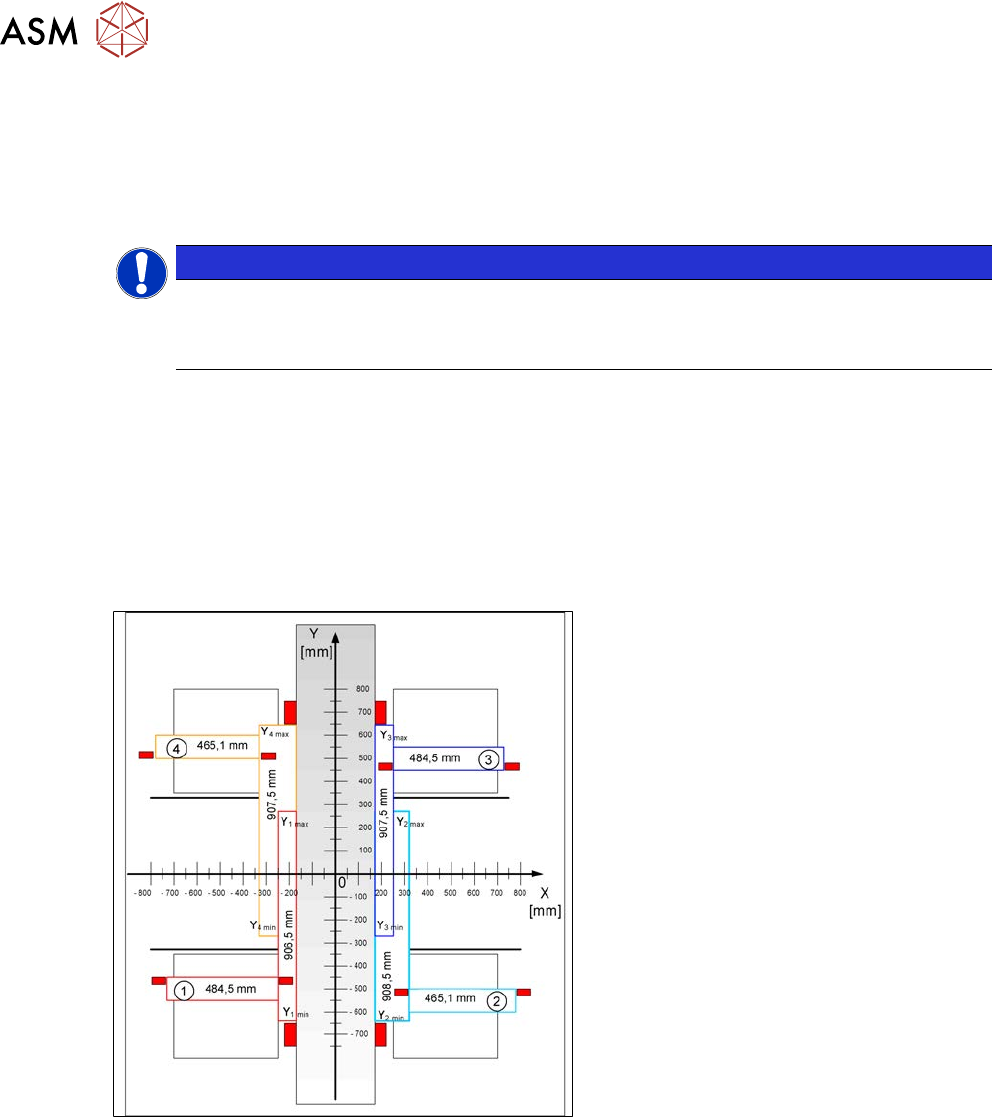
Fig.186: Travel range for X and Y axes (X series shown as
example)
1) to 4) = gantry 1 to 4
The end of the X axis travel range is + or -
0.5 mm before the software limit switch,
which is 1.5 mm before the buffer. A safety
distance of 2.0 mm to the buffer is adequate
if the X axis moves into this area with ex-
cessive speed.
The end of the Y axis travel range is + or -
2.0 mm before the software limit switch. The
Y axis travel range for a particular place-
ment area is monitored in one direction by
the software limit switch and a buffer. In the
other direction, there is a permanent ex-
change of communication between the axes
and their positions, via the SPI bus. (see
also 6.3.7 "Anticrash Function" [}152]).