00197042-04_SM_X-Serie-S_Customer_EN.pdf - 第56页
3 Power supply 3.4 Power supply and transformer module (up to serial number Gxxx) 56 Service Manual SIPLACE X-Serie S 06/2019 3.4.4 Checking the Input Voltage at the Inrush Current Limitation Board DANGER Observe the saf…
3 Power supply
3.4 Power supply and transformer module (up to serial number Gxxx)
Service Manual SIPLACE X-Serie S 06/2019 55
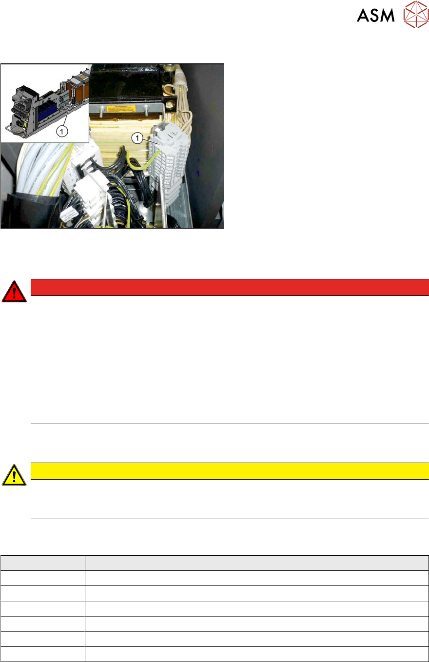
3.4.3 Checking the Input Voltage on the Transformer Module
Fig.53: Terminal panels
1. Terminal panels with primary connec-
tions for the three-phase transformer
The primary end of the three-phase trans-
former needs to be configured for the re-
spective supply voltage.
Procedure
DANGER
Observe the safety instructions
There is a risk of dangerous touch voltages and short circuits occurring in transformer mod-
ules which have been made accessible and are connected for measurement purposes.
Nonobservance of these safety instructions may cause injury to personnel and dam-
age to the machine!
Measurements may only be performed by specially trained service technicians, with appro-
priate qualifications and expertise.
► Observe in particular the sections 1.1.3 "Safety instructions for the power supply
(without SMPS)" [}12] and 1.1.4 "Safety instructions for the power supply (with
SMPS)" [}13].
► Check the terminal panel, to make sure that the primary end of the three-phase transformer is
connected correctly for the required supply voltage.
CAUTION
Power supply networks in Japan and USA
The Japanese power supply network (3x 200V~) and the power supply networks in the
USA (3x208V~) are connected to the terminals for 3x204V~.
The following overview shows the connection options for the primary voltages of the three-phase
transformer:
Terminal panel Voltage
1U1, 1V1, 1W1 415 VAC
1U3, 1V3, 1W3 400 VAC
1U4, 1V4, 1W4 380 VAC
1U5, 1V5, 1W5 230 VAC
1U6, 1V6, 1W6 220 VAC
1U7, 1V7, 1W7 204 VAC
3 Power supply
3.4 Power supply and transformer module (up to serial number Gxxx)
56 Service Manual SIPLACE X-Serie S 06/2019
3.4.4 Checking the Input Voltage at the Inrush Current Limitation Board
DANGER
Observe the safety instructions
There is a risk of dangerous touch voltages and short circuits occurring in inrush current
limiter boards which have been made accessible and are connected for measurement pur-
poses or bridging checks.
Nonobservance of these safety instructions may cause injury to personnel and dam-
age to the machine!
Measurements may only be performed by specially trained service technicians, with appro-
priate qualifications and expertise.
► Observe in particular the sections 1.1.3 "Safety instructions for the power supply
(without SMPS)" [}12] and 1.1.4 "Safety instructions for the power supply (with
SMPS)" [}13].
Overview
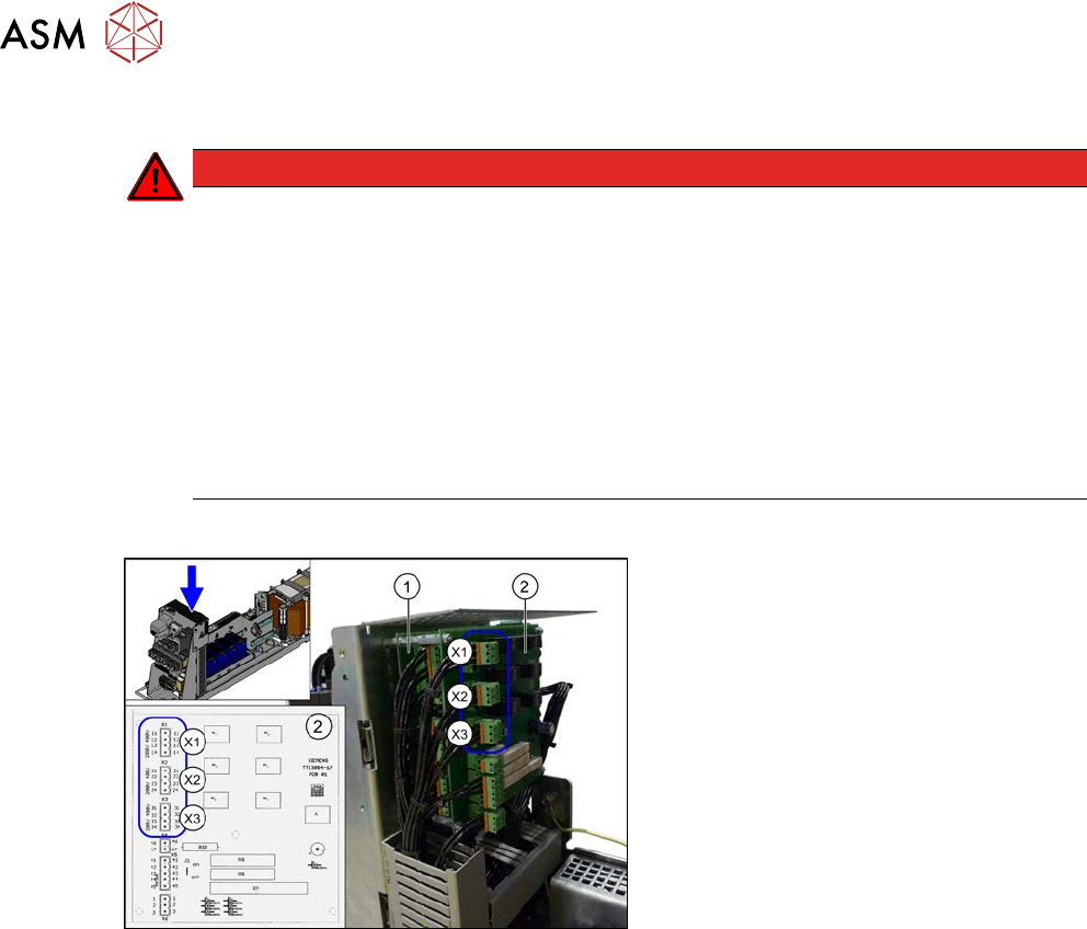
Fig.54: Overview of inrush current limiter board
1. Inrush current limiter board - servo unit
(with three connectors) (A3)
2. Inrush current limiter board - trans-
former (with six connectors) (A2)
X1, X2, X3: connectors for configuring the
inrush current limitation on the board(2)
The inrush current limiter board must be set
to 400 V, irrespective of the supply voltage.
Use plug-in jumpers for this. Observe the
label on the protective grid.
Checking/setting
► Remove the mesh cover on the boards. To do this, remove the four screws on the side of the
cover.
► Check the jumper arrangement and correct if necessary.
Take note of the position of jumper J1 (see 3.4.7 "Inrush current limiter servo (A1)" [}59]).
► Fit the protective grid into place.
3 Power supply
3.4 Power supply and transformer module (up to serial number Gxxx)
Service Manual SIPLACE X-Serie S 06/2019 57
3.4.5 Replacing the inrush current limiter for the transformer (A2)
Parts, equipment and tools
●
Inrush current limiter board transformer [03066830-xx]
Overview
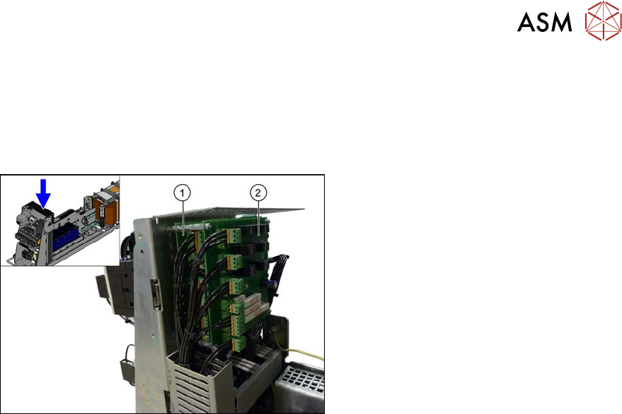
Fig.55: Overview of inrush current limiter board
1. Inrush current limiter board - servo unit
(with three connectors) (A3)
2. Inrush current limiter board - trans-
former (with six connectors) (A2)
Removal
► Switch off the machine, disconnect it from the power supply and secure it to prevent
unauthorized reactivation.
1.2 "Preparatory work..." [}16]
► Before you start working, check the power supply for absence of voltage and observe the
waiting times!
► Remove the mesh cover on the boards. To do this, remove the four screws on the side of the
cover.
► Unplug all electrical connections to the inrush current limiter transformer. Mark their positions,
to make clear assignment easier later on.
► Remove the screws fastening the inrush current limiter for the transformer and then remove
this.
Installation
► Follow the removal instructions in reverse order for installation. Also observe the following
instructions:
– Make sure that the input voltage has been set correctly at the inrush current limiter trans-
former (see label on the mesh cover).
See also
2 3.4.4 "Checking the Input Voltage at the Inrush Current Limitation Board" [}56]