00197042-04_SM_X-Serie-S_Customer_EN.pdf - 第409页
9 Component feeding 9.6 Smart Pin Support Service Manual SIPLACE X-Serie S 06/2019 409 Removal ► Switch off the machine, disconnect it from the power supply and secure it to prevent unauthorized reactivation. 1.2 "P…
9 Component feeding
9.6 Smart Pin Support
408 Service Manual SIPLACE X-Serie S 06/2019
Installation
► Follow the removal instructions in reverse order for installation. Also observe the following
instructions:
– The circlips on the holding bolts are highly sensitive. Take care when placing these on the
holding bolt.
– Set the swivel head so that the following conditions are fulfilled:
– Check the linear guide travel path. The linear guide must be easy to move along the whole
length.
– Check that the sensors switch properly. The switch tag of the linear guide must have ap-
prox. 1 mm space to the trolley.
See also
2 9.6.12 "Replacing the top sensor" [}413]
2 9.6.13 "Replacing the bottom sensor" [}414]
9.6.8 Replacing the coil hose
Parts, equipment and tools
●
Coil hose for solenoid valve [03090227Sxx]
●
Assembly instructions "Smart Pin Support" for SIPLACE X‑SeriesS [DEEN:00197394‑xx]
NOTICE
Replacing the strain reliefs
When working with the spiral hose or the spiral cable, observe the Technical Information
"Smart Pin Support: Replacing Faulty Coiled Cables at the Pin Picker (Update)" [DE:
TI2013-09D04] [EN: TI2013-09E04].
► If needed, order the following additional parts:
Cover plate/SPS [03102482-xx]
Hose holder/SPS [03102480-xx]
Overview
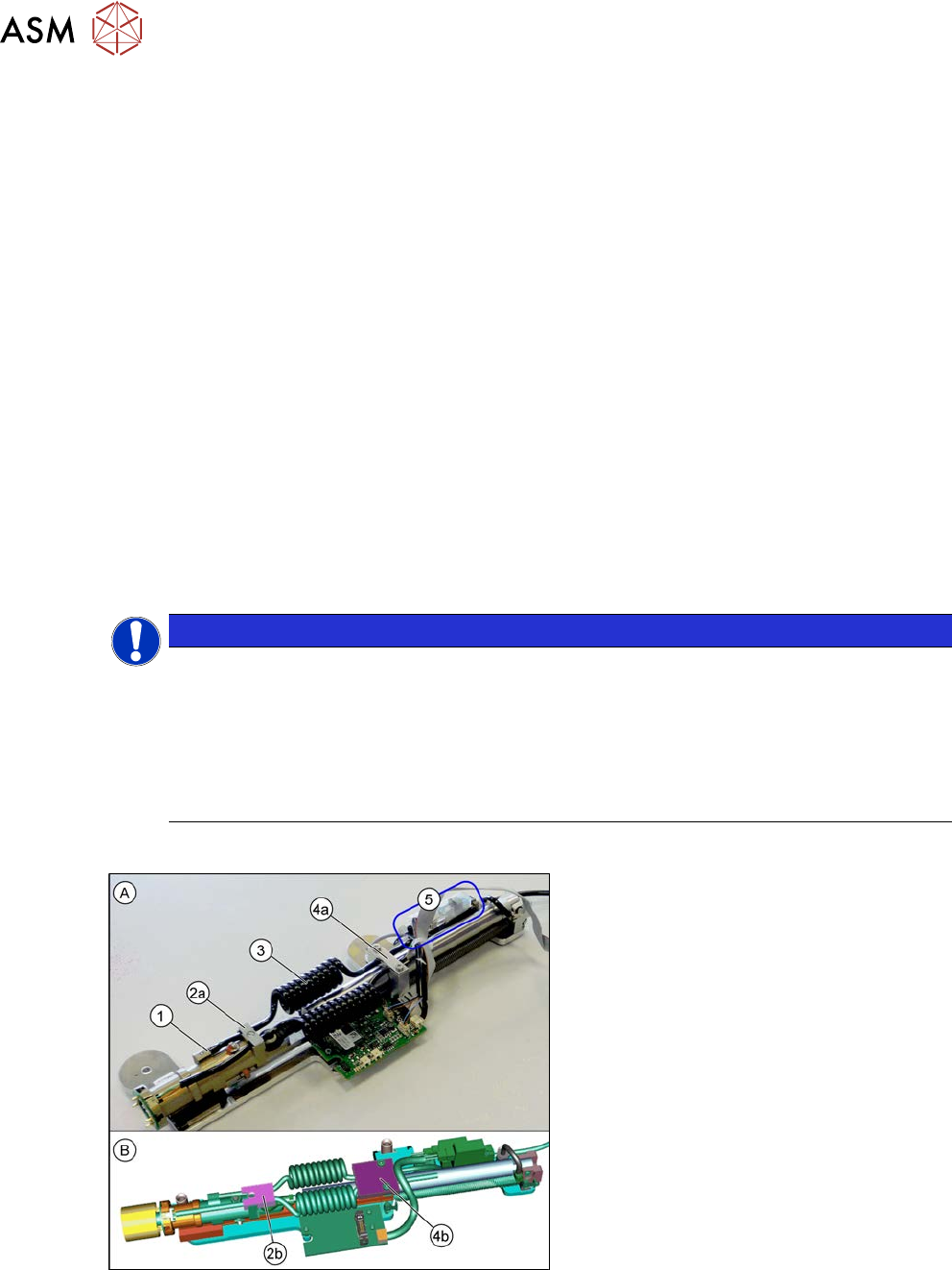
Fig.561: Coil hose – old and new version
A = Old version of Pin Picker
B = New version of Pin Picker
1. Pneumatic connection on return cylin-
der
2. Strain relief on return cylinder
2a: Old version
2b: New version
3. Coil hose
4. Strain relief on the pneumatic cylinder
guidance
4a: Old version
4b: New version
5. Valve terminal
9 Component feeding
9.6 Smart Pin Support
Service Manual SIPLACE X-Serie S 06/2019 409
Removal
► Switch off the machine, disconnect it from the power supply and secure it to prevent
unauthorized reactivation.
1.2 "Preparatory work..." [}16]
► Remove the pin picker. For more information, read section 9.6.1 "Replacing the Pin Picker
Assembly" [}399].
► Remove the strain relief on the back section of the cylinder.
► Remove the strain relief on the pneumatic cylinder guidance.
► Remove the coil hose on the pneumatic connection of the return cylinder.
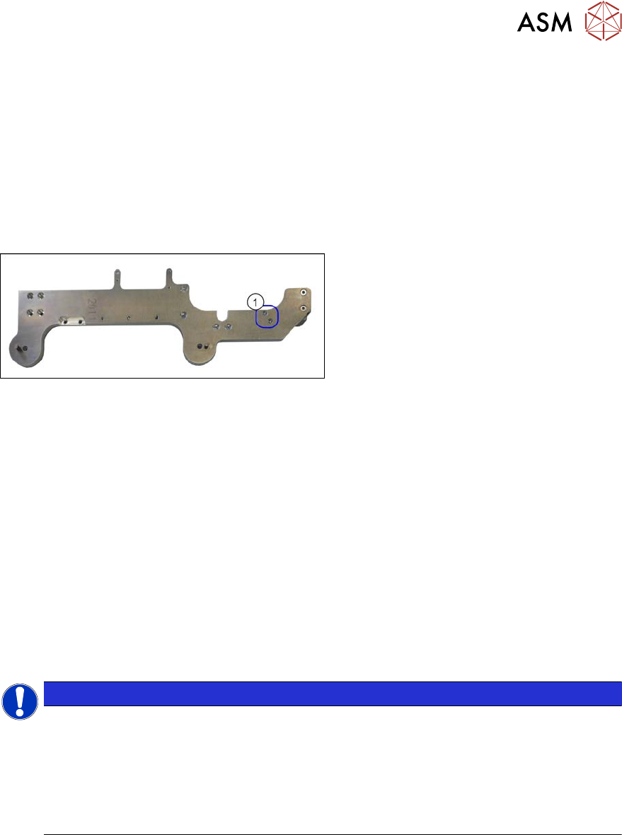
Fig.562: Screws fastening the valve terminal
► Remove the two screws(1) fastening
the valve terminal. These are on the
back of the pin picker.
► Remove the coil hose from the valve terminal.
Installation
► Follow the removal instructions in reverse order for installation. Also observe the following
instructions:
– Make sure that the coil hose does not rub against anything. It is important that the coil
hose and the coiled cable do not touch when fully extended.
9.6.9 Replacing the coiled cable
Parts, equipment and tools
●
Coiled cable [03090273-xx]
●
Safety varnish red [00318197-xx]
●
Assembly instructions "Smart Pin Support" for SIPLACE X‑SeriesS [DEEN:00197394‑xx]
NOTICE
Replacing the strain reliefs
When working with the spiral hose or the spiral cable, observe the Technical Information
"Smart Pin Support: Replacing Faulty Coiled Cables at the Pin Picker (Update)" [DE:
TI2013-09D04] [EN: TI2013-09E04].
► If needed, order the following additional parts:
Cover plate/SPS [03102482-xx]
Hose holder/SPS [03102480-xx]
9 Component feeding
9.6 Smart Pin Support
410 Service Manual SIPLACE X-Serie S 06/2019
Overview
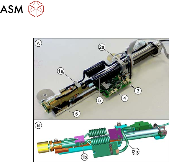
Fig.563: Coiled cable – old and new version
A = Old version of Pin Picker
B = New version of Pin Picker
1. Strain relief on back section of cylinder
1a: Old version
1b: New version
2. Strain relief on the pneumatic cylinder
guidance
2a: Old version
2b: New version
3. Coiled cable connection (on the under-
side of the control board)
4. Control board
5. Coiled cable
6. Connection of the coiled cable to the
front section of the cylinder
Removal
► Switch off the machine, disconnect it from the power supply and secure it to prevent
unauthorized reactivation.
1.2 "Preparatory work..." [}16]
► Remove the pin picker. For more information, read section 9.6.1 "Replacing the Pin Picker
Assembly" [}399].
► Remove the strain relief on the back section of the cylinder.
► Remove the strain relief on the pneumatic cylinder guidance.
► Unplug the coiled cable from the front section of the cylinder.
► Unthread the coiled cable as far as the control board.
► Unplug the coiled cable from the control board.
► Remove the coiled cable.
Installation
► Follow the removal instructions in reverse order for installation. Also observe the following
instructions:
– Make sure that the cables are run correctly.
– Make sure that the coiled cable does not rub against anything. It is important that the coil
hose and the coiled cable do not touch when fully extended.
– Secure the lower connector on the front part of the cylinder with safety varnish.
– Replace any opened cable ties.