00197042-04_SM_X-Serie-S_Customer_EN.pdf - 第218页
7 Conveyor 7.4 Conveyor Drive 218 Service Manual SIPLACE X-Serie S 06/2019 7.4 Conveyor Drive 7.4.1 Replacing the conveyor drive Parts, equipment and tools Fig.279: Spare parts for conveyor drive ● (1) DC drive motor wi…
7 Conveyor
7.3 Lifting Table
Service Manual SIPLACE X-Serie S 06/2019 217
7.3.5 Setting the Parallelism and Height of the Lifting Table Plate
DANGER
Press the EMERGENCY STOP!
Before performing adjustment work you must ensure that the lifting table has been secured
against movement!
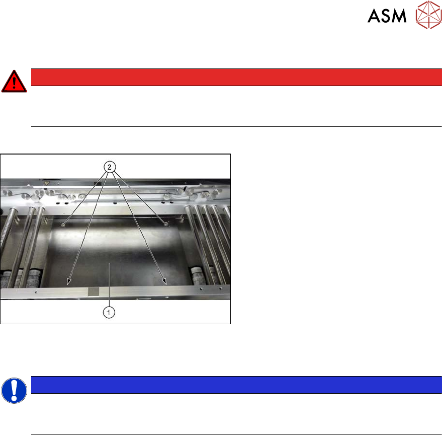
Overview
Fig.278: Lifting table plate
1. Lifting table plate
2. Fastening screws for lifting table plate
Setting
NOTICE
Single, dual conveyor
The setting is shown in the diagram using the example of a lifting table unit for the dual con-
veyor (DC). Setting the single conveyor (SC) follows the same procedure.
► Use the software to move the conveyor sides to maximum width.
7.2 "Loosening the Conveyor Side Clamps" [}207]
► Remove the screws fastening the lifting table plate (countersunk screws) but do not remove
the lifting table plate.
► Use the software to clamp the lifting table (without board).
► Underneath the fastening screws, there are setting screws (Allen key5).
Use these setting screws to set the lifting table plate so that it has no play between it and the
clamping edge.
► Check all four corners of the lifting table for any play.
► Check the setting by clamping a board into place. Check all corners to see whether there is
any play.
► Insert and tighten the four screws fastening the lifting table plate.
► Calibrate the zero position of the lifting table motor.
7 Conveyor
7.4 Conveyor Drive
218 Service Manual SIPLACE X-Serie S 06/2019
7.4 Conveyor Drive
7.4.1 Replacing the conveyor drive
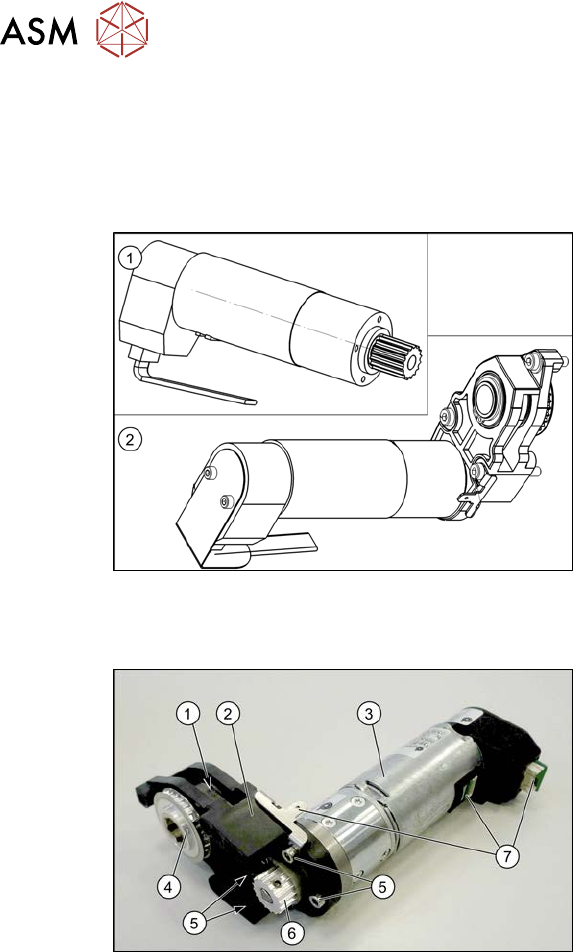
Parts, equipment and tools
Fig.279: Spare parts for conveyor drive
●
(1) DC drive motor with synchronizing
disk SXa [03093387‑xx]
or
(2) Drive unit assembly SXa
[03092345‑xx] (incl. drive bracket,
toothed belt, etc.)
●
Bearing for hexagonal shaft SXa
(plastic bearing) – pack of 10
[03092024-xx]
●
Sealing varnish Loctite 241 [02101037-
xx]
Overview
Fig.280: Overview of conveyor drive
1. Toothed belt on conveyor drive
2. Drive bracket
3. Motor
4. Drive shaft
5. Four motor fastening screws on the
drive bracket (torque = 0.7 Nm)
6. Motor shaft
7. Electrical connections (incl. shield con-
nection)
7 Conveyor
7.4 Conveyor Drive
Service Manual SIPLACE X-Serie S 06/2019 219
Removal
► Use the software to move the conveyor sides into a position which allows you best access. As
an alternative, you can loosen the clamps for the relevant sides in dual conveyors.
7.2 "Loosening the Conveyor Side Clamps" [}207]
► Switch off the machine, disconnect it from the power supply and secure it to prevent
unauthorized reactivation.
1.2 "Preparatory work..." [}16]
► Loosen the hexagonal shaft on the belt drive/conveyor drive (motor), so that you can move
the hexagonal shaft freely. To do this, dismantle the hexagonal shaft fixture on one side and
the corresponding plastic bearing on both sides.
7.6.6 "Replacing the hexagonal shaft" [}253]
► Loosen the movable idler pulley.
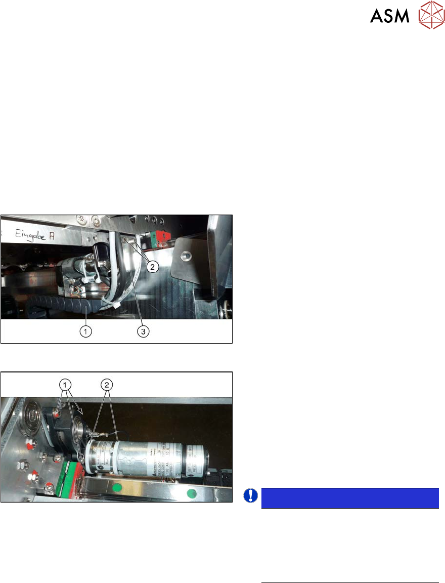
Fig.281: Holding plate
► To achieve a greater movement range,
it may be advisable to loosen the two
screws(2) fastening the retaining
plate(3) to the trailing cable(1).
These fastening screws are located on
the conveyor side opposite to the con-
veyor drive.
Fig.282: Cable ties and fastening screws
► Remove the two cable ties(2). You
may want to mark their positions for
easier replacement later on. Also pay
attention to the position of the cable
ties heads.
► Remove the three screws(1) (Allen key
3) fastening the conveyor drive. While
doing this, carefully unthread the con-
veyor drive from the conveyor belt.
NOTICE!
There is a washer under the top
fastening screw. This needs to be
placed back in when refitting.
These three fastening screws are
tightened with a torque of 1.7 Nm dur-
ing refitting.
.
► Remove the two screws fastening the cover plate above the connectors of the conveyor drive
and remove the cover plate.
► Unplug all electrical connections from the conveyor drive. If necessary, mark their positions to
make clear assignment easier later on. Loosen the corresponding cable ties, if required.
► Remove the conveyor drive and drive holder from the machine.
► Remove the four screws fastening the conveyor drive to the drive bracket.
► Carefully unthread the motor from the toothed belt.