00197042-04_SM_X-Serie-S_Customer_EN.pdf - 第122页
4 Electrics and control system 4.7 Replacing the button 122 Service Manual SIPLACE X-Serie S 06/2019 4.7 Replacing the button Parts, equipment and tools Fig.147: Overview of button 1. Pushbutton 2. EMERGENCY STOP button…
4 Electrics and control system
4.6 Replacing the monitor/monitor holder
Service Manual SIPLACE X-Serie S 06/2019 121
4.6 Replacing the monitor/monitor holder
Parts, equipment and tools
●
Monitor SCD1520-TDC [03078913-xx]
●
Monitor holder [03042042‑xx]
●
Standard tooling
●
Torx screwdriver ESD 1.0-5.0 Nm [03078400-xx]
●
Bit holder for TorqueVario screwdriver [03078706-xx]
Overview
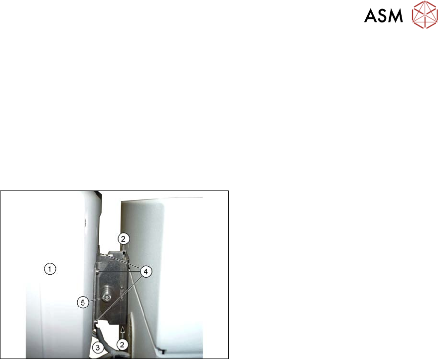
Fig.146: Overview of monitor
1. Monitor
2. Screws fastening the monitor holder to
the machine
3. Monitor connections
4. Screws fastening the monitor to its
holder
5. Screw (joint)
(torque 4.5Nm)
Removal
► Switch off the machine, disconnect it from the power supply and secure it to prevent
unauthorized reactivation.
1.2 "Preparatory work..." [}16]
► Unplug all connections to the monitor. You may want to mark their positions, to make clear as-
signment easier later on.
► Loosen the upper and lower screws fastening the monitor bracket to the machine and lift the
monitor and its bracket out of the keyholes.
► Remove the four screws fastening the monitor to its bracket and then remove the monitor
bracket.
Installation
► Follow the removal instructions in reverse order for installation. Also observe the following
instructions:
– First tighten the screw (joint) with a torque of 4.5Nm.
4 Electrics and control system
4.7 Replacing the button
122 Service Manual SIPLACE X-Serie S 06/2019
4.7 Replacing the button
Parts, equipment and tools
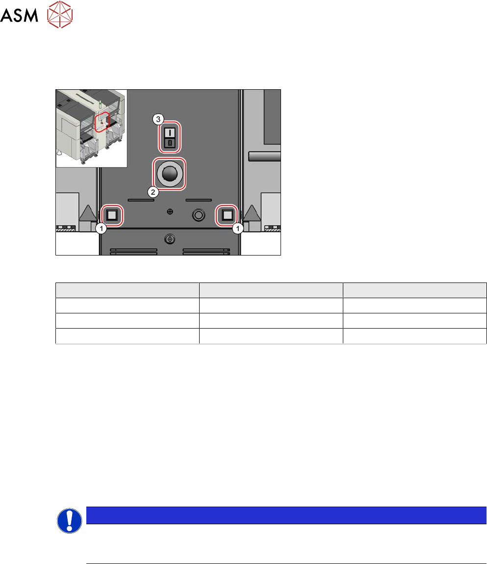
Fig.147: Overview of button
1. Pushbutton
2. EMERGENCY STOP button
3. Twin pushbutton
Square shape Round shape
Pushbutton 00334095‑xx 03164001Sxx
EMERGENCY STOP button 00334073‑xx 03165966Sxx
Twin pushbutton 03084513‑xx 03170336Sxx
Removal
► Switch off the machine, disconnect it from the power supply and secure it to prevent
unauthorized reactivation.
1.2 "Preparatory work..." [}16]
► Remove the relevant button. To do this, unplug all electrical connections. You might like to
mark their positions to make clear assignment easier later on.
Installation
► Follow the removal instructions in reverse order for installation.
4.8 Replacing the CAN switch
NOTICE
Only X-Series S up to No. Gxxxx
The CAN switch and the upgrade kit are only used in SIPLACE X-Series S machines up to
serial no. Gxxxx.
Parts, equipment and tools
●
CAN switch [03083844-xx] or
Upgrade kit PCB conveyor CAN switch X-Series S [03106370-xx]
4 Electrics and control system
4.8 Replacing the CAN switch
Service Manual SIPLACE X-Serie S 06/2019 123
Overview
The CAN switch is located at location 1 in the machine frame.
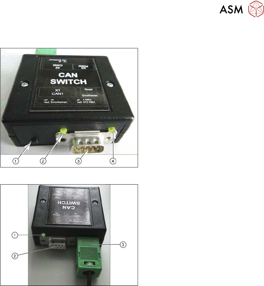
Fig.148: CAN switch, front
1. Reset button
The button is used to reset the red LED
on both sides, CAN 1 and CAN2.
2. LED green: setting 1Mbit
LED red: setting 500kBit
3. CAN bus cable connection CAN 1
4. LED green/red for CAN 1
Data transfer OK: green
Error frames received: red
Fig.149: CAN switch, back
1. LED green/red for CAN 2
Data transfer OK: green
Error frames received: red
2. CAN bus cable connection CAN 2
3. Voltage supply connection 24 V DC
Removal
► Switch off the machine, disconnect it from the power supply and secure it to prevent
unauthorized reactivation.
1.2 "Preparatory work..." [}16]
► Unplug the electrical connections for the CAN switch. You may want to mark the positions of
these connections to make clear assignment easier later on.
Installation
► Follow the removal instructions in reverse order for installation. Also observe the following
instructions:
– Check/correct the DIP switch setting on the CAN switch (see 4.8.1 "Setting the DIP Switch
on the CAN Switch" [}124]).
The DIP switch is preset for the SIPLACE X‑SeriesS as a default.