00197042-04_SM_X-Serie-S_Customer_EN.pdf - 第190页
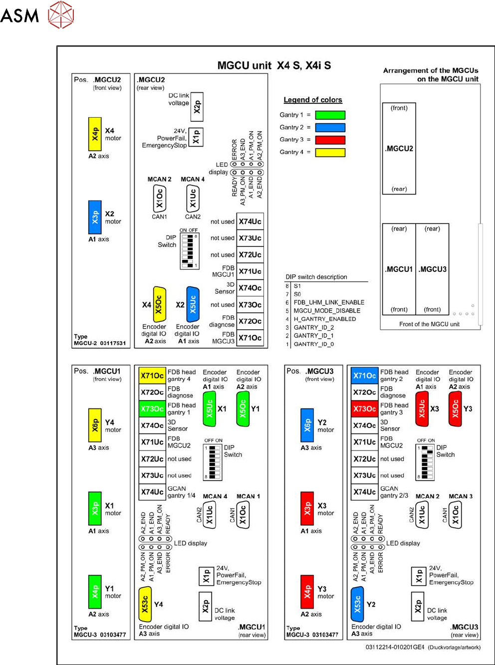
6 Gantries 6.5 GCU and MGCU 190 Service Manual SIPLACE X-Serie S 06/2019 Fig.239: Overview of MGCUs on X4 S and X4i S
6 Gantries
6.5 GCU and MGCU
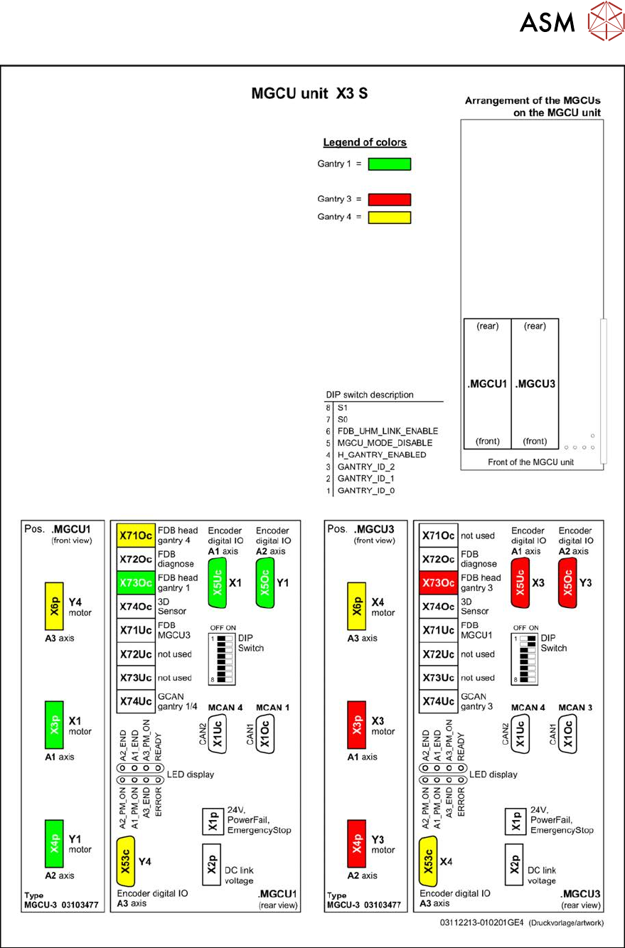
Service Manual SIPLACE X-Serie S 06/2019 189
Fig.238: Overview of MGCUs on X3 S
6 Gantries
6.5 GCU and MGCU
190 Service Manual SIPLACE X-Serie S 06/2019
Fig.239: Overview of MGCUs on X4 S and X4i S
6 Gantries
6.6 HCU, MHCU, boards and camera
Service Manual SIPLACE X-Serie S 06/2019 191
6.6 HCU, MHCU, boards and camera
6.6.1 Replacing the MHCU, basic and head adapter
Parts, equipment and tools
The following spare parts can be replaced:
●
MHCU assembly compatible [03090990Sxx] from FS04
(from FS04 the MHCU also replaces the HCU assembly [03054884-xx].)
●
PCB / X base adapter C&P [03045647Sxx] from FS08
●
Module / X base adapter TWIN [03062201Sxx]
Machine Head Adapter Number of MHCU, base adapters
SX4/DX4,
X-Series
S to
Gxxxx
CP20A,
CPP
Module X base adapter C&P
[03071420-xx]
1x MHCU from FS04 or HCU
1x PCB / X base adapter C&P
[03045647Sxx]
Twin Head adapter Twin HCU /
SX4
[03082096-xx]
2x MHCU from FS04 or HCU
1x module/ X base adapter TWIN
[03062201Sxx]
X-Series
S from
no.:
Hxxxx
CP20A,
CPP
Module X base adapter C&P
[03071420-xx]
1x MHCU [03090990Sxx] from FS04
1x PCB / X base adapter C&P
[03045647Sxx] from FS08 *
CP20P Module X base adapter
CP20P
[03109399-xx]
1x MHCU [03090990Sxx] from FS04
1x PCB / X base adapter C&P
[03045647Sxx] from FS08 *
Twin Head adapter Twin HCU /
SX4
[03082096-xx]
2x MHCU [03090990Sxx] from FS04
1x module/ X base adapter TWIN
[03062201Sxx]
* You need a PCB/X base adapter C&P [03045647Sxx] with FS08 or higher. From FS08 onwards,
longer flat ribbon cables are needed. These are provided in [03045647Sxx].
Removal
NOTICE
HCU / MHCU
If the term "HCU" is mentioned, all descriptions also apply to the "MHCU". Any relevant dif-
ferences will be mentioned explicitly.
► Switch off the machine, disconnect it from the power supply and secure it to prevent
unauthorized reactivation.
1.2 "Preparatory work..." [}16]
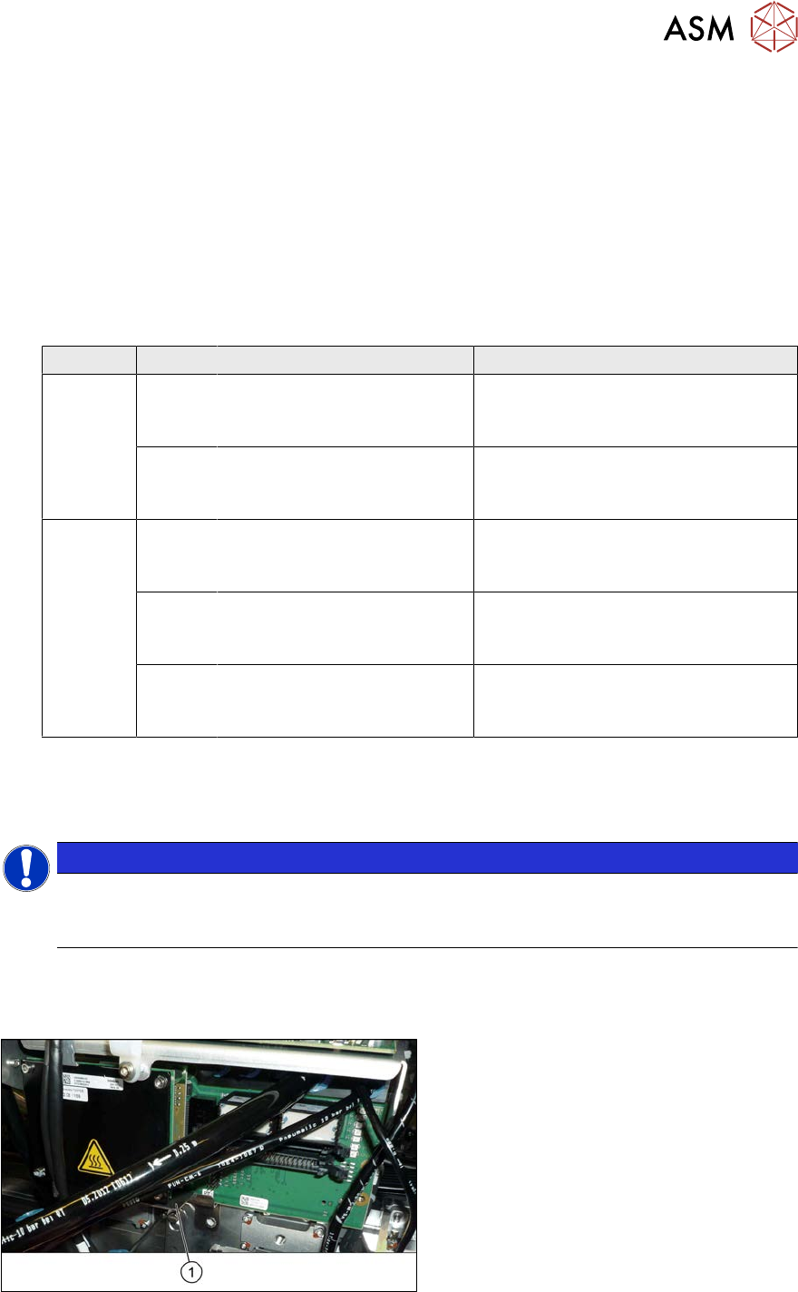
Fig.240: Protective plate
► You may need to dismantle the place-
ment head for better access. Read the
relevant chapter, section 8 "Head ex-
change" [}305], if required.
► Remove the two screws fastening the
protective plate(1) (if present) and
remove the protective plate.