00197042-04_SM_X-Serie-S_Customer_EN.pdf - 第198页
6 Gantries 6.7 Filter and pneumatics 198 Service Manual SIPLACE X-Serie S 06/2019 6.7 Filter and pneumatics 6.7.1 Replacing the vacuum distributor on the placement head Parts, equipment and tools ● Distributor placement …
6 Gantries
6.6 HCU, MHCU, boards and camera
Service Manual SIPLACE X-Serie S 06/2019 197
Overview
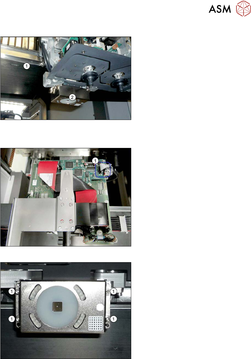
Fig.248: Overview of PCB camera
1. Gantry
2. PCB camera
The PCB camera is located on the under-
side of the gantry, on the head mount.
Removal
Fig.249: Connecting cable
► Unplug the two connection cables X2
and X6(1) from the Vision board and
unthread as far as the PCB camera.
You may like to mark their positions, to
make clear assignment easier later on.
Fig.250: PCB camera
► Remove the four screws (1) holding the
PCB camera. Mark the position to
make clear assignment easier later on.
Installation
► Install the new PCB camera on the mount. Secure the screws with Loctite 241.
► Run the connection cable to the Vision board and reconnect to the electrical system.
► After replacing the PCB camera, you will need to recalibrate the whole machine. Use the rel-
evant software function in the Service menu.
6 Gantries
6.7 Filter and pneumatics
198 Service Manual SIPLACE X-Serie S 06/2019
6.7 Filter and pneumatics
6.7.1 Replacing the vacuum distributor on the placement head
Parts, equipment and tools
●
Distributor placement head vacuum [03029190-xx]
CAUTION
Use the correct blanking plugs
► Only use blanking plugs in the machine which match the manufacturer's compressed
air connection. A tight fit cannot be guaranteed for other blanking plugs.
► We recommend the use of blanking plugs made by Festo.
Overview
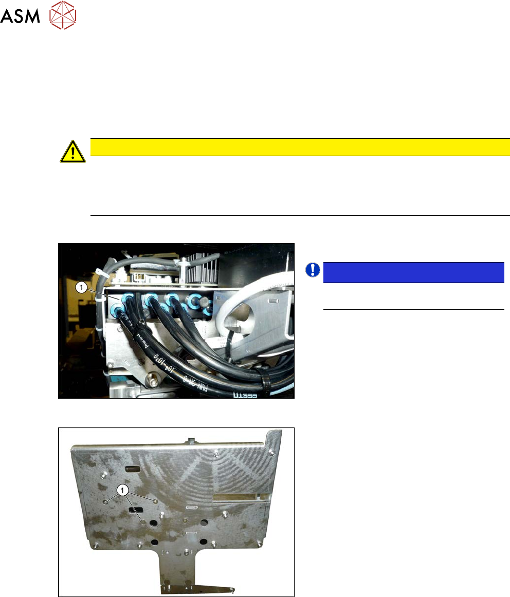
Fig.251: Overview of vacuum distributor
1. Vacuum distributor
NOTICE!
There may still be a pressure sensor
on the vacuum distributor.
.
See 6.7.2 "Replacing the pressure
sensor" [}199].
Fig.252: Screws fastening the vacuum distributor
1. Screws fastening the vacuum distrib-
utor
The screws fastening the vacuum distributor
are located under the head interface.
Removal
► Switch off the machine, disconnect it from the power supply and secure it to prevent
unauthorized reactivation.
1.2 "Preparatory work..." [}16]
► Switch off the compressed air supply
5.2 "Disabling the compressed air supply" [}134]
► Dismantle the Vision board spread spectrum (see 6.4.7 "Replacing the Vision board spread
spectrum HCU" [}178]).
► Dismantle the head interface (see 6.4.5 "Replacing the Head Interface" [}172]).
6 Gantries
6.7 Filter and pneumatics
Service Manual SIPLACE X-Serie S 06/2019 199
► Mark all pneumatic connections to the vacuum distributor, to make clear assignment easier
later on.
► Unplug all pneumatic connections to the vacuum distributor.
► Remove the screws fastening the vacuum distributor and then remove the vacuum distributor.
Installation
► Follow the removal instructions in reverse order for installation.
6.7.2 Replacing the pressure sensor
Parts, equipment and tools
●
Upgrade kit - pressure sensor for vacuum SIPLACE C&P20P [03108457‑xx]
Overview
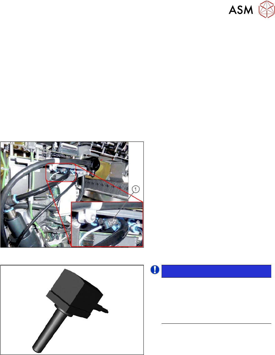
Fig.253: Pressure sensor on the gantry
1. Pressure sensor
The pressure sensor is located on the
vacuum distributor of the gantry and is con-
nected to the head interface (X8) adapter.
Fig.254: Pressure sensor
NOTICE!
The pressure sensor is only needed
when a vacuum pump and CPx heads
are installed.
In this case, the pressure sensor is es-
sential for operation of the placement
machine.
.
Removal
► Switch off the machine, disconnect it from the power supply and secure it to prevent
unauthorized reactivation.
1.2 "Preparatory work..." [}16]
► Switch off the compressed air supply
5.2 "Disabling the compressed air supply" [}134]
► Unplug the electrical connection of the pressure sensor to the head interface (X8).
► Disconnect the pressure sensor from the vacuum distributor on the gantry.
Installation
► Follow the removal instructions in reverse order for installation.