APPENDIX.pdf - 第11页
Appendix A Optimizer A-5 A.3. Setup Menu/Nozzle Figur e A-3. "Optimizer Setup: Nozzl e" dialog box The screen to set the optimum arrangem ent of nozzles. All the nozzles registered in the equipment are display …

Samsung Component Placer CP-45F(V)/FS Operations Manual
A-4
of arranged tape feeders and the number of feeders to be arranged are displayed.
<COMP> column
Of the components used by the PCB being edited, tape feeder components are
displayed here.
<#> column
Displays the number of placement points for each component. You can refer to it
when you decide the number of feeders to arrange.
<ARG> column
Displays the number of feeders already arranged on the feeder lane for each
component. This number is the same with the number of feeder lanes in the left list
box.
<AVL> list box
Displays the number of feeders to be arranged by the Optimizer for each component.
<LIM> list box
Displays the sum of the feeders displayed in the <ARG> and <AVL> columns for
each component. In other words, it is the limit number of feeders that can be assigned
to each component. The minimum value is 1.
<Limit> button
Used to specify the number of feeders to be used for each component. If 1 feeder is
arranged for a component, entering 3 in this box and pressing the limit button makes
the number in the AVL column to 2. The Optimizer arranges up to 2 new feeders. Set
an appropriate number of feeders while considering the number of placement points
for each component. To get a better operation efficiency, allocate more feeders for the
components that have many placement points.
Arrow button(
)
Used to change the setting of an arranged feeder to the setting of a feeder to be
rearranged by the Optimizer.
<Remove Tape> button
Click on the <Remove Button> to ignore all the tape feeders already arranged and to
arrange new tape feeders. As this button is present at the bottom of the Optimizer
setting screen, it can be selected although the tape feeder setting tap is not displayed.
Appendix A Optimizer
A-5
A.3. Setup Menu/Nozzle
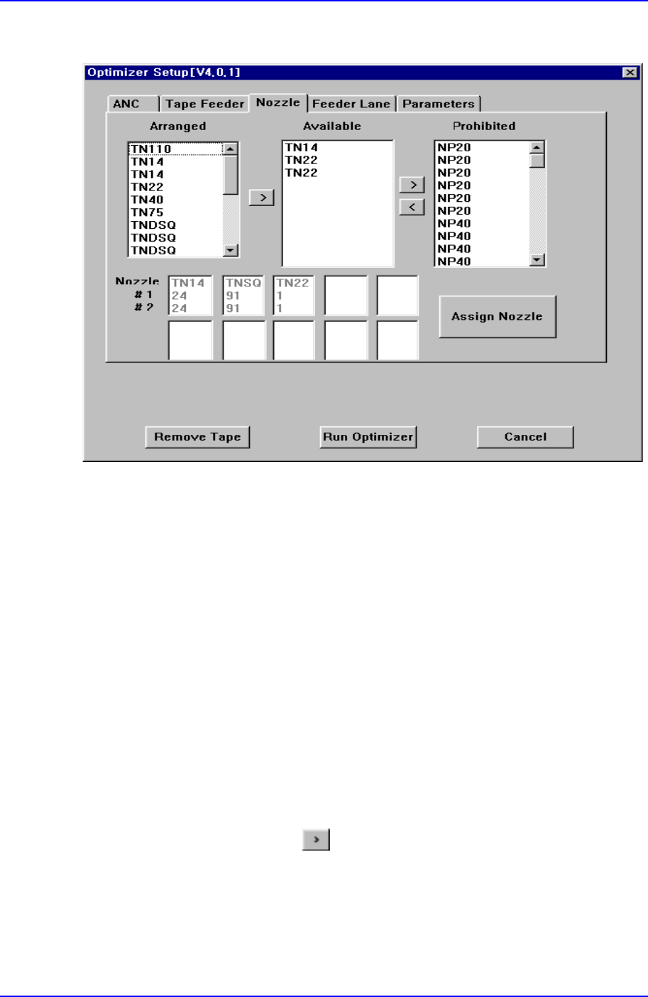
Figure A-3. "Optimizer Setup: Nozzle" dialog box
The screen to set the optimum arrangement of nozzles.
All the nozzles registered in the equipment are displayed in the <Arranged>, <Available>,
or <Prohibited> list box. The sum of nozzles in each list box is the same with the sum of
the heads (in the case of CP-45, it is 6). The user can set a desired number of nozzles to
be arranged by the Optimizer by adjusting the number of nozzles in the <Available> list
box.
<Nozzle> group/<Arranged> list box
The user can arrange nozzles in the ANC pocket directly in the ANC Setup Dialog
Box. The nozzles arranged in advance are displayed in the <Arranged> list box. The
nozzles listed here are used for operation but the Optimizer does not arrange them in
the pocket arbitrarily. To rearrange the nozzles already arranged by using the
Optimizer, select the desired nozzle and move it to the <Available> list box by
clicking on the arrow button (
). If the user wants to arrange the nozzle directly
again, the user needs to display the ANC Setup Dialog box and specify the pocket.
<Nozzle> group/<Available> list box
The list box to specify the nozzles to be arranged in the pocket by the Optimizer. In
Samsung Component Placer CP-45F(V)/FS Operations Manual
A-6
the case of Figure A.3, when the Optimizer is executed, TN14 nozzle arranges 1
nozzle and TN22 arranges 2 nozzles in the empty nozzle pockets. The number of
nozzles to be arranged by the Optimizer can be increased and decreased between the
<Available> list box and the <Prohibited> list box by clicking on the arrow buttons
and .
<Nozzle> group/<Prohibited> list box
This list box works like a buffer for unnecessary nozzles. The nozzles that do not
need to be rearranged can be placed in the <Prohibited> list box.
<Nozzle> group/ <Nozzle #1 #2> list box
All the nozzles used for the PCB being edited are displayed in this list box and the
status of each nozzle being the first operation nozzle or the second operation nozzle
for the component is displayed at the same time. #1 indicates the sum of placement
points of the component assigned to the first operation nozzle and #2 the sum of
placement points of the component assigned to the second nozzle.
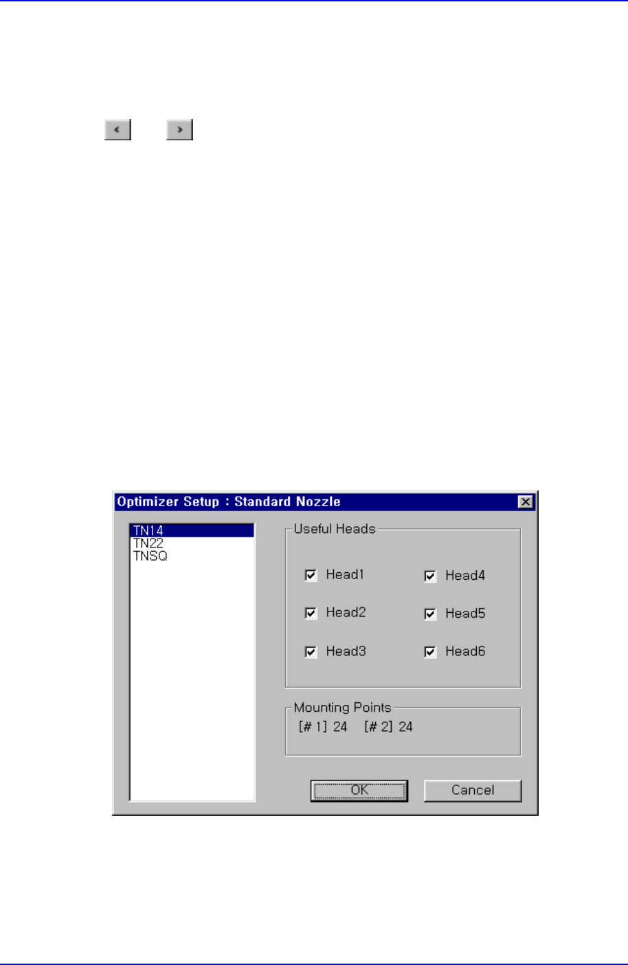
<Assign Nozzle> button
Used to assign applicable heads for each nozzle separately. When this button is
clicked on, the following dialog box is displayed.
Figure A-4. "Optimizer Setup: Standard Nozzle" dialog box