APPENDIX.pdf - 第20页
Samsung Component Placer CP-45F(V)/FS Operations Manual A-14 program based on the optimization solution searched so far is created. A.7. Optimization Result When the Optimizer execution is completed, the following dialog…
Appendix A Optimizer
A-13
A.6. Optimizer Dialog
Press the <Run Optimizer> button to execute the Optimizer. During the execution, the
following dialog box is displayed.
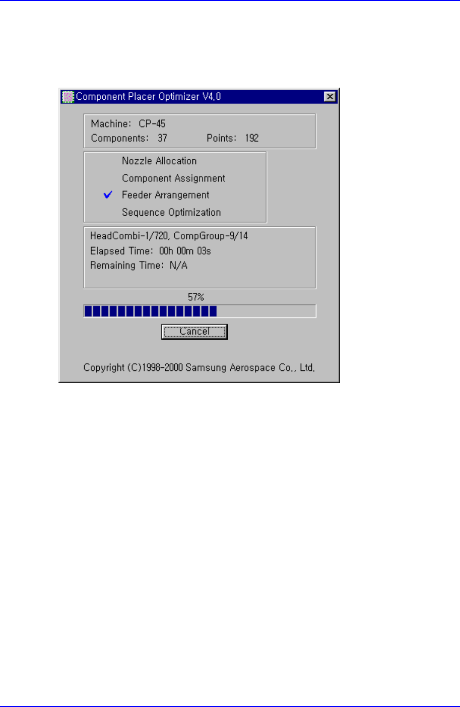
Figure A-7. "Optimizer" dialog box
In the top box, equipment model name, the number of component types, and total
placement points are displayed. In the second box, the steps of Optimizer progression are
displayed with a check mark. The one with the check mark is the step in progress. In the
third box, more detailed progression status, elapsed time and remaining time are
displayed. Remaining time is displayed only in the sequence optimization step when the
search depth option is set to Deep. The more the number of component types and
placement points, the longer the execution time. The progress bar under the third box
shows the progress of the current step. The Cancel/Stop button on the bottom is used to
stop the execution of Optimizer in the middle. Normally Cancel is shown on the button,
when this button is pressed in this status, the User Break message box is displayed and
the Optimizer execution is cancelled. In other words, all the operation executed thus far is
cancelled. However, if Deep is selected for the search depth in the Optimizer execution
option, Stop is displayed during sequence optimization. At this time, even though this
button is pressed, the optimization solution searched so far is preserved and a dialog box
according to this result is displayed. When the Accept button is clicked on here, a step
Samsung Component Placer CP-45F(V)/FS Operations Manual
A-14
program based on the optimization solution searched so far is created.
A.7. Optimization Result
When the Optimizer execution is completed, the following dialog box is displayed.
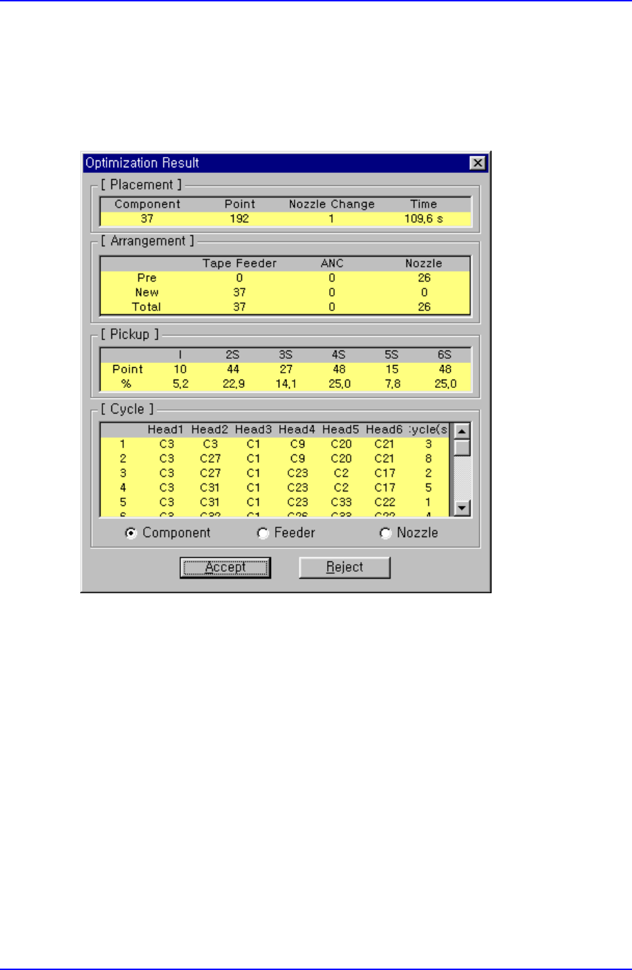
Figure A-8. "Optimization Result" dialog box
This dialog box shows various results so that the optimized status can be seen at a glance.
When the <Accept> button is clicked on, closes this dialog box, ends the Optimizer and
the result is reflected in the MMI step program. When the <Reject> button is clicked on,
the result is not reflected in the MMI step program and the Optimizer option dialog box is
displayed again. If necessary, readjust the Optimizer options and execute again.
<Placement> group
The number of component types, total placement points, the number of nozzle
changes, and total operation time is displayed in this group. As the total operation
time is an estimate based on simulation, it might differ from the actual operation time.
To calculate production quantity, actually produce a PCB with the equipment and
refer to that time.
<Arrangement> group

Appendix A Optimizer
A-15
The arrangement status of tape feeders, ANCs, and nozzles is displayed in this group.
Pre indicates the number arranged by the user, New indicates the number newly
arranged in the Optimizer, and Total indicates the total number of arrangements.
<Pickup> group
The distribution of simultaneous component pickups is displayed in this group. As
the CP-45 model has 6 heads, there are 6 types of component pickups, from
individual pickup to 6 simultaneous pickups. The number of pickup points and its
percentage for each pickup type is displayed in this group.
I: Component pickup by one head only (individual pickup)
2S: Component pickup by two heads simultaneously
3S: Component pickup by three heads simultaneously
6S: Component pickup by six heads simultaneously
<Cycle> group
The status of component allocation, feeder allocation, and nozzle allocation in the
final step program is displayed in this group. Three radio buttons on the bottom let
the user to select one and see the allocation status. The number in the rightmost
column displays the number of cycle repetitions.
Component: In the component allocation status, the component to be operated by
each head is displayed with cx, x is the number given to a component. (Component
name is not displayed here)
Feeder: In the feeder allocation status, the feeder lane from which the head picks up
is displayed. The front feeder base is indicated by Fx, and the rear feeder base by Rx.
Here x is the feeder lane number. And, the stick feeder is indicated by Sx, and tray
feeder by Tx, here x is not a feeder unit name but a division by pickup point.
Nozzle: The nozzle allocation status shows which nozzle is used for which head.
The name of the nozzle to be used by each head is displayed.