APPENDIX.pdf - 第67页
Appendix D. Docking Cart D-3 D.1.3.3. Feeder In the CP-45 series, any type of Feeder that can be mounted on the Feeder Base can be mounted. Pneumatic T ape Feeder ty pe: 8,12,16,24,32,44,56mm (Reel Size: MAX 380mm but …
Samsung Component Placer CP-45F(V)/FS Operations Manual
D-2
DC-Feeder Base Ass’y
It is where the Feeder is mounted and a locating Bush is attached.
Component placer
The Docking Cart System can be mounted on it and a locating Pin for DC Feeder
Base and a Clamp Cylinder for locking are attached.
D.1.2.1. Specifications
Table D-1. Specifications
Classification Specification Remark
Height of the feeder's
pickup point
900mm ± 20, 952.5±12.5
Option
Number of mounted feeders 48 / DC-FEEDER BASE Based on the 8mm Pneumatic
Tape feeder
Dimension
770(L)×927(W)× 965mm(H)
Weight About 130Kg
Docking cart
Maximum
Load
150Kg 8mm feeder(48 units) + feeder
base
Dimension
880(L) ×210(W) ×225mm(H)
Feeder Base
Weight 50Kg
The size of component
placer when the D/C is
installed
1,660(L) × 1,830(W) ×1,408(H)mm
D.1.3. Applicable range
D.1.3.1. Component Placer
In the CP-45 series, it only applies to machines that have the Docking Cart option.
D.1.3.2. Software
Runs on MMI Version 2.108, VME 2.3 or later versions.
Control the front and rear options.
Checking the change of the maximum number of mounted feeders.
Checking the state of supplying the air with the docking cart.

Appendix D. Docking Cart
D-3
D.1.3.3. Feeder
In the CP-45 series, any type of Feeder that can be mounted on the Feeder Base can be
mounted.
Pneumatic Tape Feeder type: 8,12,16,24,32,44,56mm
(Reel Size: MAX 380mm but 330mm when the machine with 900mm height as the
height of PCB transport rail use the tape cutter device)
Stick Feeder: Multi Vibration, Multi Belt, Stack Belt
D.2. Operation Method
D.2.1. Prerequisites
After the Feeders are batch changed by the Docking Cart, the following items should be
checked for regular surface mounting operation.
Safety conditions of the machine when changing the Feeder Base.
OFFSET following the change of each Feeder Base.
D.2.2. Preparation
D.2.2.1. Setting the height of the Docking Cart
To set the height of the docking cart , perform the following steps.
1. Connect the air coupling to supply the compressed air.
2. Unscrew the fixed bolt to have the shaft turn.
3. Adjust the upper limit by rotating the shaft and then have the left shaft and the right
shaft with equal height.
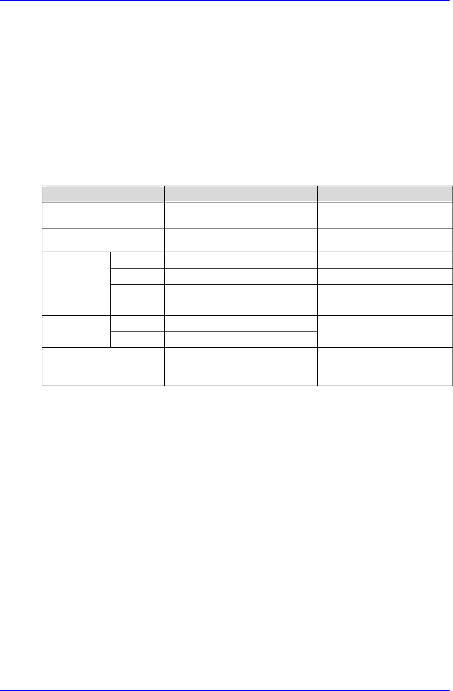
4. While referring to Figure 2-1, control the height of the DC-Feeder Base by raising the
Docking Cart(set it so that the bottom of the DC-Feeder Base is about 2mm higher than
the low stopper).
5. Rotate the nut for setting the low limit so that can keep the height of the docking cart
be about 5mm away from the DC-Feeder Base and then lock the nut for setting the low
limit.
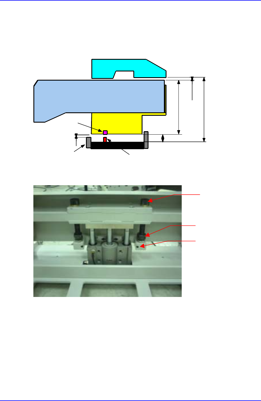
6. While referring to Figure 2-2, screw the fixed bolt to keep the shaft from turning.
7. Raise the Docking Cart to the highest point and plug it into the machine.
Samsung Component Placer CP-45F(V)/FS Operations Manual
D-4
8. Check if there is a problem with docking In/Out operation.
9. If needed , adjust the speed controller to have the desired speed since the more feeder
take the more time to keep the docking cart up and the less time to keep it down
3mm
11mm
6mm
TAPE FEEDER
ALIGN BODY
DC-FEEDER BASE
PIN
BUSH
LOW LIMIT
STOPPER
A+17mm
A
Figure D-2. Setting the height of the docking cart
Figure D-3. The cylinder up
Shaft
Nut
The bolt for locking shaft