APPENDIX.pdf - 第9页
Appendix A Optimizer A-3 A.2. Setup Menu/T ape Feeder Figur e A-2. "Optimizer Setup: T ape Feeder" dialog box The screen to set the optimum arrangement of tape feeder . The Optimizer can arrange tape feeders in…
Samsung Component Placer CP-45F(V)/FS Operations Manual
A-2
Displays the ANCs already arranged in the feeder lane of the "PCB Setup" dialog box.
The Optimizer does not change the arrangement position of the ANCs listed here and
arranges the tape feeder so that there is no mechanical interference with the arranged
ANCs. Move the ANC, for which you want the Optimizer to show the optimum
position, to the <Available> list box by selecting it in the list and clicking on the
arrow button (
).
<ANC> group/<Available> list box
The group to list the ANCs for which you want optimum arrangement among the
ANCs registered in the "PCB Setup" dialog box. When the Optimizer is executed, the
listed ANCs are arranged on the optimum positions on the feeder lane. Move the
ANC that is not necessary for the PCB file being edited to the <Prohibited> list box
by selecting it and clicking on the arrow button (
).
<ANC> group/<Prohibited> list box
The group to list the ANCs that are not necessary to be arranged by the Optimizer
(unnecessary for the PCB being edited). The ANCs listed in this box are not
considered for optimum arrangement by the Optimizer and they are considered as
non-existent. Therefore, the ANCs listed in this box must be removed from the feeder
lane. Move the ANC that needs to be optimally arranged to the available list box by
selecting it and clicking on the arrow button (
).
<Run Optimizer> button
When this button is pressed, executes the Optimizer. After executing this button, do
not execute other MMI commands until Optimizer execution has been completed and
the MMI screen is displayed again.
Appendix A Optimizer
A-3
A.2. Setup Menu/Tape Feeder
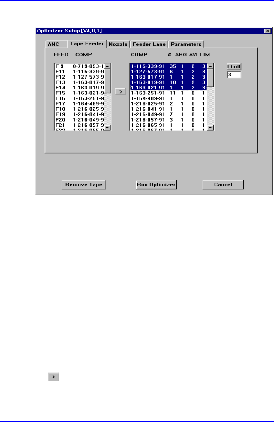
Figure A-2. "Optimizer Setup: Tape Feeder" dialog box
The screen to set the optimum arrangement of tape feeder. The Optimizer can arrange
tape feeders in the optimum feeder lanes by considering simultaneous pickup and
operation time. But the user must specify the installation position for tray feeders and
stick feeders.
<FEED COMP> list box
In the left list box, the number of the feeder that is already arranged in the feeder lane
and each component name are displayed. For the front feeder base, F is attached in
front of the feeder lane number and for the rear feeder base, R is attached in front of
the feeder lane number. The feeders listed here are not arranged arbitrarily by the
Optimizer. However, the feeders already arranged affect other feeders when they are
arranged by the Optimizer. That is, when there are feeders already arranged, new
feeders are arranged to increase simultaneous pickup.
Among the feeders displayed here, move the feeders for which you want optimal
arrangement by the Optimizer to the right list box by clicking on the arrow button
(
) and execute the Optimizer.
<COMP # ARG AVL LIM> list box
In the right list box, the number of placement points for each component, the number

Samsung Component Placer CP-45F(V)/FS Operations Manual
A-4
of arranged tape feeders and the number of feeders to be arranged are displayed.
<COMP> column
Of the components used by the PCB being edited, tape feeder components are
displayed here.
<#> column
Displays the number of placement points for each component. You can refer to it
when you decide the number of feeders to arrange.
<ARG> column
Displays the number of feeders already arranged on the feeder lane for each
component. This number is the same with the number of feeder lanes in the left list
box.
<AVL> list box
Displays the number of feeders to be arranged by the Optimizer for each component.
<LIM> list box
Displays the sum of the feeders displayed in the <ARG> and <AVL> columns for
each component. In other words, it is the limit number of feeders that can be assigned
to each component. The minimum value is 1.
<Limit> button
Used to specify the number of feeders to be used for each component. If 1 feeder is
arranged for a component, entering 3 in this box and pressing the limit button makes
the number in the AVL column to 2. The Optimizer arranges up to 2 new feeders. Set
an appropriate number of feeders while considering the number of placement points
for each component. To get a better operation efficiency, allocate more feeders for the
components that have many placement points.
Arrow button(
)
Used to change the setting of an arranged feeder to the setting of a feeder to be
rearranged by the Optimizer.
<Remove Tape> button
Click on the <Remove Button> to ignore all the tape feeders already arranged and to
arrange new tape feeders. As this button is present at the bottom of the Optimizer
setting screen, it can be selected although the tape feeder setting tap is not displayed.