APPENDIX.pdf - 第71页
Appendix D. Docking Cart D-7 7. Keep the docking cart valve down. While lowering the Feeder Base, make sure the machine’ s Locator Pin is correctly inserted into the Feeder Base Pin Hole. 8. Operate the mechanical valve …
Samsung Component Placer CP-45F(V)/FS Operations Manual
D-6
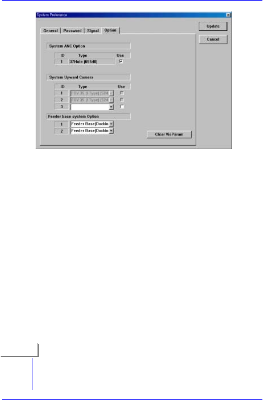
Figure D-5. Setting the feeder base system option
D.3. Installation Method
D.3.1. Order of Changing the Docking Cart
To change the docking cart , perform the following steps.
1. Push the F/FEEDR Change switch on the front side of the machine to have the
machine be in ADJUST Mode. And then Make sure that the head move to the safety
zone.
2. Operate the mechanical valve to have the clamp cylinder released.
3. Connect the air hose to the docking cart and keep the valve up to raise the docking cart.
4. Separate the docking cart from the machine.
5. Change the feeders on the DC-Feeder Base.
6. Plug the docking cart into the machine completely and then push the stopper to lock
the docking cart.
The air hose closer to the check valve should be connected to the docking cart and then
you connect it to the machine. When the Docking Cart is installed on the machine, the
Docking In angle should be under 30°.
Caution
Appendix D. Docking Cart
D-7
7. Keep the docking cart valve down. While lowering the Feeder Base, make sure the
machine’s Locator Pin is correctly inserted into the Feeder Base Pin Hole.
8. Operate the mechanical valve to have the clamp cylinder clamped.
You should disconnect the air hose closer to the machine first.
D.4. Maintenance
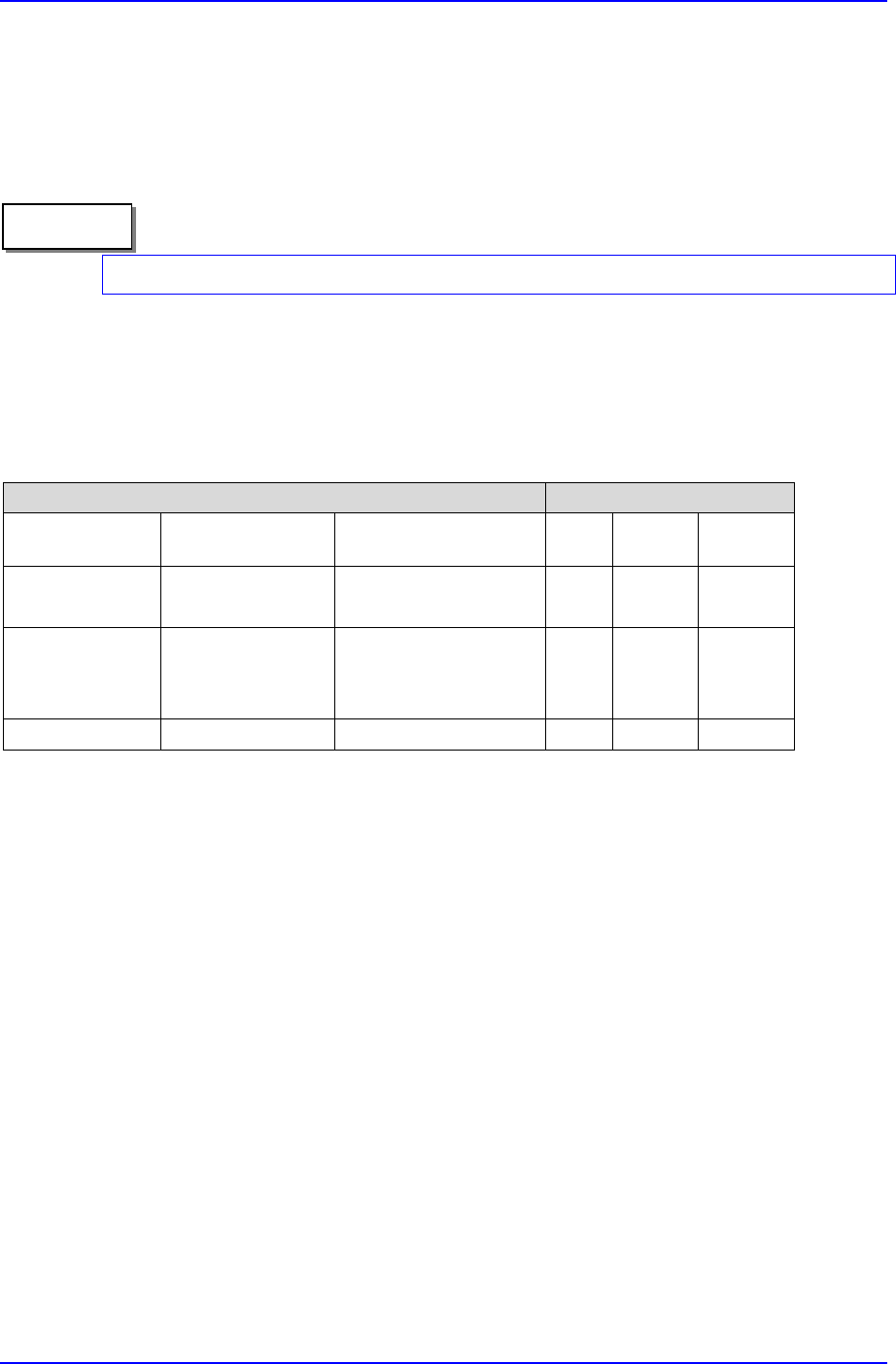
Table D-2. Items to check
Items to check Checking Interval
Large unit of
classification
Small unit of
classification
Items to check Daily Weekly Monthly
Driving area
Winner Bearing
Guide Rail
Uncleanness, oil supply
Uncleanness, oil supply
0
0
Air Speed Control
Air Cylinder
Whole piping
Operational Speed
Operational State
Air Leakage
0
0
0
Other Caster Abrasion 0
Caution
Samsung Component Placer CP-45F(V)/FS Operations Manual
D-8
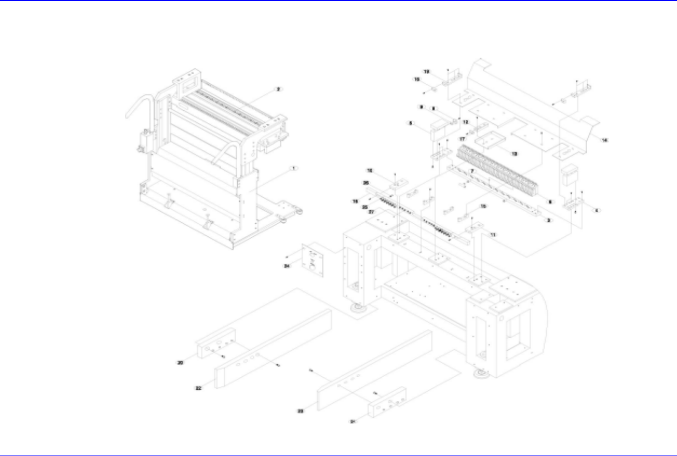
D.5. Technical Drawing & Air Diagram
D.5.1. Technical Drawing & Part List
Figure D-6. Technical drawing