APPENDIX.pdf - 第14页
Samsung Component Placer CP-45F(V)/FS Operations Manual A-8 A.4. Setup Menu/Feeder Lane Figur e A-5. "Optimizer Setup: Feeder Lane" dial og box The screen to set the feeder lane to be used for feeder arrangemen…

Appendix A Optimizer
A-7
Basically all nozzle types can be applied to any head, therefore all heads are checked.
But there are occasions when a certain nozzle has to be operated in a certain head.
Also, this can be used when the user wants to assign a certain head to a certain nozzle.
The above figure shows the nozzle TN14 can operate on any head between Head1
and Head6.
<Useful Heads> check box group
The heads that can be used by the selected nozzle type. As a standard, check so
that Head1, Head2, Head3, Head4, Head5, and Head6 can be used.
<Mounting Points> group
This group shows the number of components used by the nozzle selected for the
current PCB. This can be used as a reference data when the user assigns the
applicable heads to each nozzle. #1 shows the total number of placement points
of the component for which #1 nozzle is selected and #2 shows the total number
of placement points of the component for which #2 nozzle is selected.
<OK> button
Saves the selected options and closes the dialog box.
<Cancel> button
Cancels the selected options and closes the dialog box.
Samsung Component Placer CP-45F(V)/FS Operations Manual
A-8
A.4. Setup Menu/Feeder Lane
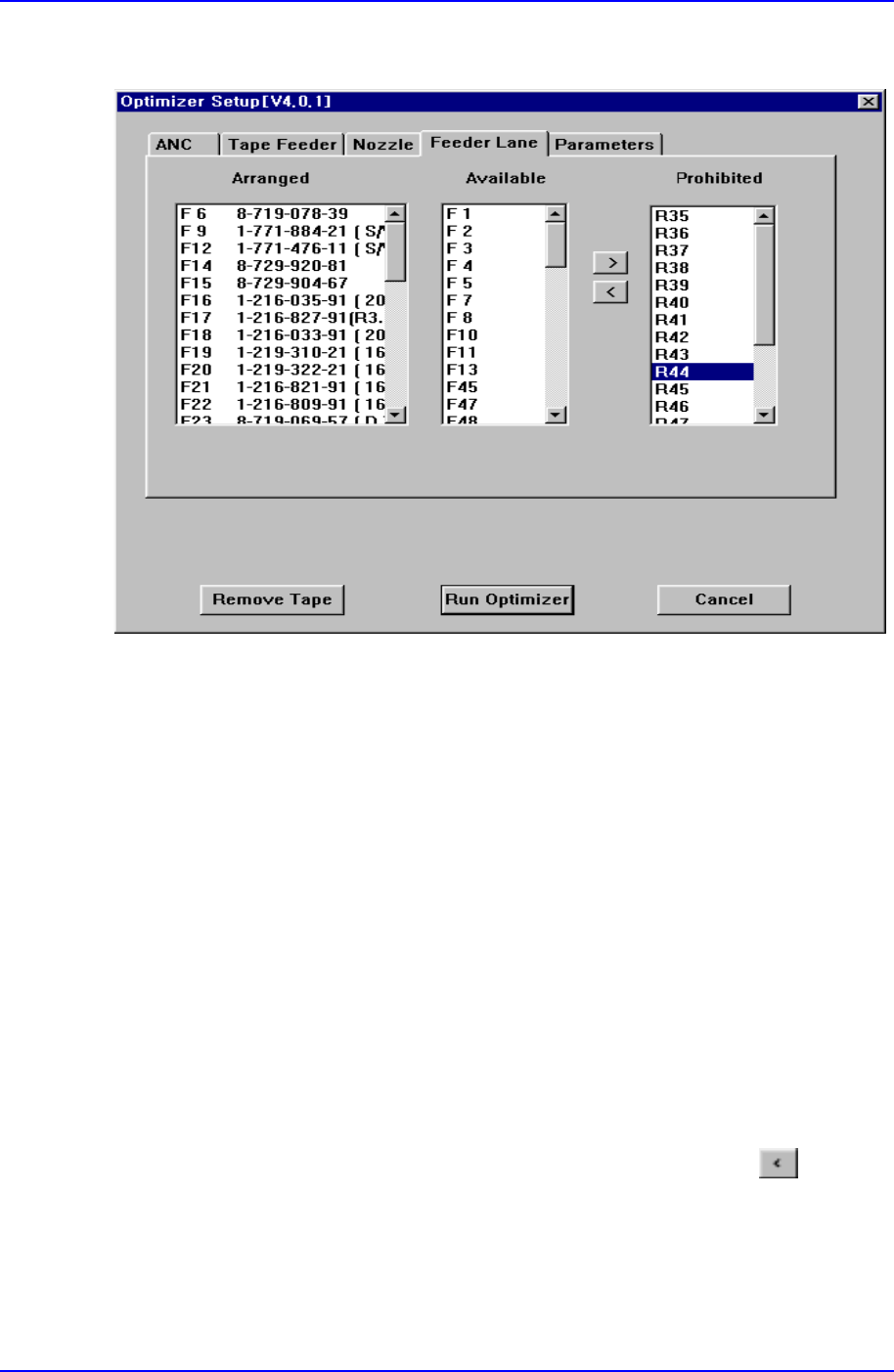
Figure A-5. "Optimizer Setup: Feeder Lane" dialog box
The screen to set the feeder lane to be used for feeder arrangement by the Optimizer. The
devices that can be arranged on the feeder lane are tape feeders, stick feeder units,
movable ANCs, camera units fixed on the feeder lane. This screen shows the current
arrangement status on each feeder lane. The feeder lanes on which devices shouldn't be
arranged in the Optimizer can be specified.
<Arranged> list box
Displays the status of already installed feeder lanes, installed tape feeders, movable
ANCs, and cameras. The F in the feeder lane number indicates the front feeder base,
R indicates the rear feeder base.
<Available> list box
Displays the feeder lanes on which the Optimizer can arrange tape feeders, stick
feeder units, movable ANCs, and fixed type camera units. If you don't want to
arrange any device on a certain feeder lane, click on the arrow button
and move
it to the <Prohibited> list box.
<Prohibited> list box
Specify the feeder lanes on which you don't want to arrange any feeder unit, ANC, or
camera, so that they are displayed in this group. No device is arranged by the

Appendix A Optimizer
A-9
Optimizer on the feeder lanes listed here. But you don't need to specify each lane in
the <Prohibited> list box while considering the width of the feeder unit, ANC, and
camera unit. The Optimizer is set to consider the width of the device to be arranged
on the feeder lane so that there is no mechanical interference. Use the arrow buttons,
and to move between the <Available> list box and the <Prohibited> list
box.