晶圆测试说明书Cascade-11861-6-Manual.pdf - 第28页
4 • Summit 11K/12K Probe Station User’s Guide M ICROSOFT W INDOWS - B ASED S OFTWAR E 12000-Series Only You control your probe station using Mi crosoft Windows-based software, which includes online help . The software in…
Chapter 1: Station Overview
•
3
• Probe station controls reside outside the enclosed area to provide easy access
to probe positioners, the microscope and positioning controls.
Interlock Switches for Access Door
To protect you from hazardous voltages on the chuck, the MicroChamber
provides two access-door interlock switches. The software-controlled switch
closes when the MicroChamber access door closes, and opens when the access
door opens. In addition, a hardware interlock BNC is on the right rear of the
probe station (fig. 9 on p. 26 and fig. 10 on p. 26). You must connect a cable from
the BNC connector to the interlock connector on the chuck-biasing power supply.
PRECISION POSITIONING
12000-Series Only
The closed-loop position feedback system provides micron accuracy for test
measurements. Submicron moves enable you to test the smallest wafer
geometries. Stepper motors ensure fast and quiet X-Y-Z positioning.
COMPUTER CONNECTION
12000-Series Only
System electronics are integrated into the probe-station's base, with a single
control cable connecting the station to the computer.
See also, the Facility and Computer Requirements section for more information
about the minimum computer configuration.
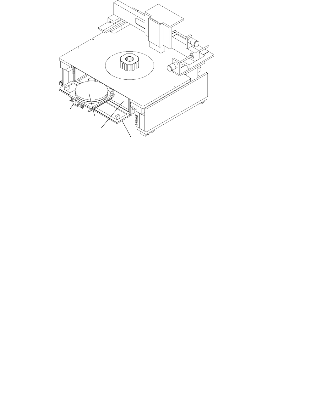
Fig. 3. MicroChamber, access door, and roll-out stage.
Roll-out
stage
handle
Chuck
MicroChamber
MicroChamber
access door
4
•
Summit 11K/12K Probe Station User’s Guide
MICROSOFT WINDOWS-BASED SOFTWARE
12000-Series Only
You control your probe station using Microsoft Windows-based software, which
includes online help. The software includes:
• Probe station control software (PCS or Nucleus) that enables you to manage
the probe station and prepare it for automatic testing. See the Nucleus or PCS
User’s Guides for detailed software information.
• Self-test utility to verify hardware
• Probe plan editor that enables point-and-click die selection
• Optional WinCal VNA calibration software that enables you to use any
standard vector network analyzer
NOTE
Many software test applications are available to work with prober control software,
such as HP VEE, Metrics I/CV, Labview, Basic for Windows, Visual Basic, HPIC-
CAP, BSim Pro, V+most, etc. Call CMI Customer Support for details.
As a true Microsoft Windows application, the software includes:
• Dynamic link and data exchange server (DDE), which enables other Windows
programs to control the probe station
• GPIB, which enables a remote host to control the probe station
X-Y STAGE
The stage has manual controls for moving in the X and Y-axes. There is also a
theta control for rotating the chuck (fig. 4).
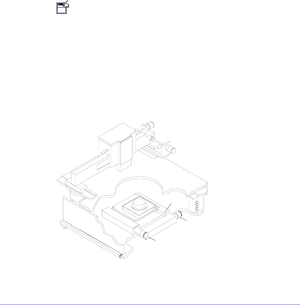
Fig. 4. X-Y Stage and theta Controls.
Y-axis Control
X-axis Control
Theta Control

Chapter 1: Station Overview
•
5
Roll-Out Stage
The roll-out stage handle, when unlocked and pulled, moves the stage to the front
(travel: 25 cm) of the probe station (fig. 3 on p. 3). With the stage in this forward
position, you can safely load and unload wafers.
CAUTION
Make sure the Z-lever is up when you pull the rollout stage handle. Otherwise, you
can scrape probes across the chuck and substrate, which will damage the wafer
and probes.
Rotating the Chuck
The chuck rests on a rotary stage, enabling you to rotate it ±7° (1° per turn). Turn
the theta control to rotate the chuck (fig. 4).
CONNECTION PANELS
Optional probe connection panels (at the rear of the platen) provide a convenient
attachment point for test instruments. The connection panels relieve cable strain
and enable you to make stable measurements.
There are two versions— the large-area microscope bridge mount and the high-
stability microscope bridge mount.
The large-area bridge mount includes a removable vacuum panel, which has six
pairs of barb connectors and switches, enabling you to connect up to six vacuum-
mounted positioners.
The high-stability tilt-back bridge mount uses a fixed vacuum connection panel.
Triaxial and BNC feed-through connectors are available, as well as banana-jack to
pin-jack connectors. Use of the triax and BNC connectors, and the banana posts
on the probe station, reduce strain on the probes and cables. They also limit probe
cable movement, which provides additional measurement stability. The triax and
BNC connectors interface from front to back, directly across the panel. The
banana-post and pin-jack connectors are color-coded to indicate internal
connections. Cables are attached from the probes to the front connectors and from
your measurement devices to the rear connectors.
The shorting link grounds the top of the station when it is connected. If you have
trouble with ground loops, you can disconnect the shorting link without
damaging your test equipment or creating hazardous working conditions.
Isolation diodes limit voltage on the platen to ±0.7 V to protect you and your test
equipment.