晶圆测试说明书Cascade-11861-6-Manual.pdf - 第34页
10 • Summit 11K/12K P robe Station User’s Guide • For high-frequenc y measurem ents, Cascade recommends: • DC and RF positioners • HPC-series probes or ACP-series probes • RF cables, elbows, and accessories E NVIR ONMENT…
Chapter 1: Station Overview
•
9
THERMAL CHUCK CONTROLLER & AIR DRYER
(11600, 12600, 11700, 12700)
PROBE CARD ADAPTER
Standard Accessories
Your station will come with a large assortment of accessories, such as a contact
substrate, dust cover, etc., in addition to those accessories listed below.
11100, 12100
11500, 12500, 11600, 12600, 11700, 12700, 11800, 12800
NOTE
Cascade recommends that you install a triax-shorting plug whenever the station is
not in use to prevent charges from building up in the chuck. We also recommend
that you install the triax-shorting plug when you are not measuring substrate
current or biasing the chuck.
Recommended Configurations
For DC or capacitance measurements, Cascade recommends:
• DCM vacuum-base or fixed-base DC and RF positioners with low current
(LC) triax adapters
• DCP probes in standard or Kelvin configurations
• LC cables and accessories for low-level measurements
Available temperature ranges -65 °C to 200 °C or 0 °C to 200 °C (300
°C for HT versions)
Air dryer option available yes
Manufactured by Temptronic Corp.
Probe card dimensions 4.5-inch wide
Manual Wrench set
Appropriate power cords for country
of use (12100)
Manual Wrench set
Microscope eyepiece covers Appropriate power cords for country of use
Microscope grounding clip Interlock cable
Triax cap (N/A for 11100,
12100, 11600, 12600)
Triax shorting plug (N/A for 11100, 12100, 11600,
12600)

10
•
Summit 11K/12K Probe Station User’s Guide
• For high-frequency measurements, Cascade recommends:
• DC and RF positioners
• HPC-series probes or ACP-series probes
• RF cables, elbows, and accessories
ENVIRONMENTAL CONDITIONS
Your probe station works safely in the same environment as your PC. Use the
probe station under the following environmental conditions:
• Indoors only
• Altitude up to 2000 m
• Temperature 5 °C to 40 °C
• Maximum relative humidity 80% for temperatures up to 31 °C decreasing
linearly to 50% relative humidity at 40 °C
• Main supply voltage fluctuations not to exceed ± 10% of the nominal voltage
CAUTION
A total current of 3.2/1.6 A is required for both auxiliary and microscope outlets.
The combined leakage current of accessories attached to these two outlets must
be less than 2.85 mA.
Thermal Controls
(11600, 11700, 11800, 12600, 12700, and 12800 Only)
These thermal probe stations include the thermal chuck with a chuck bias
connection located at the left back of the MicroChamber. The thermal controller
and cooler/circulator, and air dryer are options.
See thermal
controller
documentation for
more information
on thermal
equipment controls
THERMAL CONTROLLER AND COOLER/CIRCULATOR
The thermal controller and cooler/circulator maintain the desired test
temperature of the thermal chuck. A power cable heats the chuck. The cooler/
circulator pumps coolant fluid through the chuck to chill it.
The MicroChamber access door includes an interlock switch that you can connect
to a warning indicator. This indicator prevents injury if the chuck is at a thermal-
extreme when the MicroChamber door is open.
AIR DRYER
The air dryer unit dehumidifies the air used to purge the MicroChamber. This
prevents frost from forming during cooling. Alternatively, you can use dry
nitrogen or another inert gas to purge the MicroChamber.
THERMAL CHUCK
The thermal chuck is electrically isolated from the rest of the probe station.
Chapter 1: Station Overview
•
11
On the Summit 1X600-series, you can apply a bias voltage or ground the chuck
surface through the BNC connector located at the left back of the MicroChamber.
The center of the BNC connector carries the chuck surface bias or guard voltage.
The outer shield of the BNC connector provides a connection to the
MicroChamber.
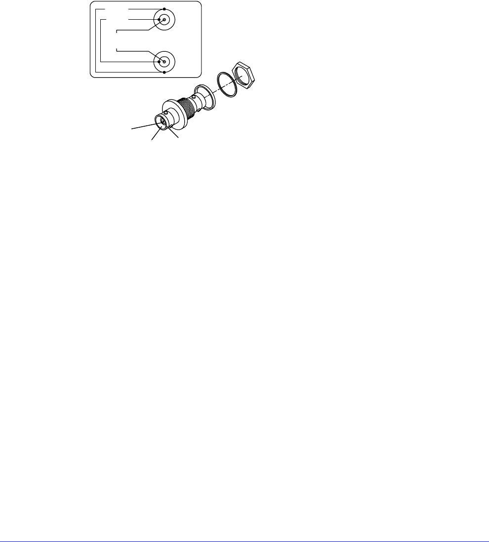
On the Summit 1X700 and 1X800-series, you can apply a bias or guard voltage, or
ground the chuck surface through two Kelvin-type triax connectors — located at
the left-back of the MicroChamber.
Fig. 8. Force, guard, and shield connections.
MicroChamber
connection
Chuck guard-layer
connection
Chuck surface
connection
Shield
Guard
Force/
Sense
Triax to Chuck