晶圆测试说明书Cascade-11861-6-Manual.pdf - 第74页
50 • Summit 11K/12K Probe Station User’ s Guide Safety interlock switch To protect you from hazardous voltages and temperature extrem es on the chuck, the MicroChamber acce ss-door has a BNC safety inte rlock switch. Thi…
Chapter 3: Installing •
49
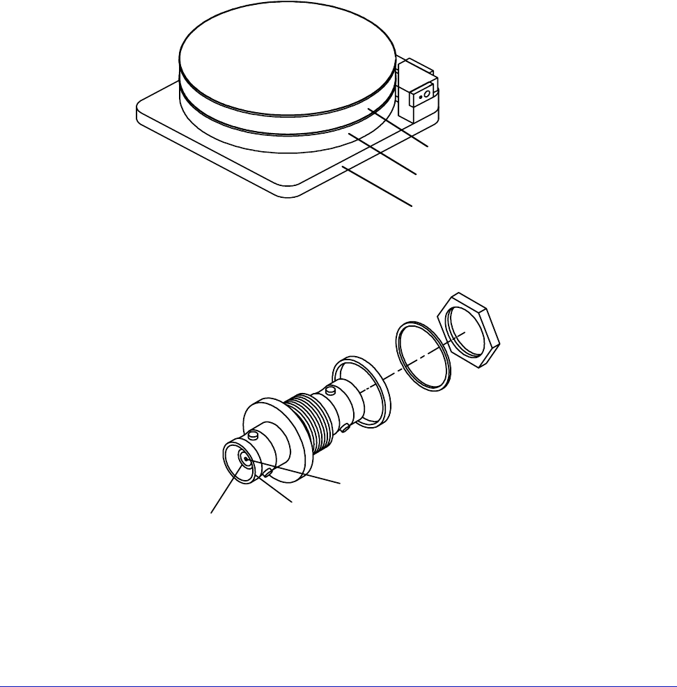
The chuck is composed of three layers: shield, guard, and surface (fig. 37). This
structure electrically isolates the surface from the rest of the station, enabling you
to use guarded measurement techniques for accurate and rapid current
measurements. Two triax connectors enable you to apply a bias voltage to the
chuck's surface and a guard voltage to the chuck's guard layer.
The chuck-bias triax connectors are located on the back of the station (fig. 38).
• The outer shield of the triax connector makes an electrical connection with the
MicroChamber and the shield layer of the chuck.
• The middle shield of the connector makes a connection to the guard layer of
the chuck (FemtoGuard or AttoGuard)
• The center connector makes a connection with the chuck surface
.
Fig. 37. Chuck layers.
Surface layer
Guard layer
Shield layer
Fig. 38. Chuck triaxial connectors.
Chuck surface
connection
MicroChamber
connection
Chuck guard-layer
connection

50
• Summit 11K/12K Probe Station User’s Guide
Safety interlock switch
To protect you from hazardous voltages and temperature extremes on the chuck,
the MicroChamber access-door has a BNC safety interlock switch. This switch is
closed when the MicroChamber access door is closed and open when the access
door is open. The interlock BNC is located on the back right of the probe station
(see fig. 9 and fig. 10). You must connect a cable from the BNC connector to the
interlock connector on the chuck-biasing power supply and warning indicator.
The MicroChamber door also has a software interlock that can be set to one of
four modes within prober control software (PCS or Nucleus).
THERMAL EQUIPMENT INSTALLATION
Table 2. Probe station, thermal unit cable, and hose connections.
* If you ordered the GPIB option, you'll have to put the GPIB switch box between the
Cable or Hose From To
coolant lines fittings on back of
probe station
fittings on back of
cooler/circulator
thermal power cable MicroChamber power
cable on probe station
THERMAL DEVICE on the
back of the Temptronic
controller
control cable CONTROL INPUT on
back of cooler/
circulator
COOLER on the back of
the Temptronic
controller
controller power cable Temptronic controller 20 Amp (115V) power
source, or 10 Amp
(230V)
air hose air source COMPRESSED AIR INPUT
on air dryer
air hose REGULATED OUTPUT DRY
AIR FLOW on air dryer (if
ordered), or your dry air
supply
air fitting on back of
MicroChamber
GPIB Cable (if you
ordered this option)
See the GPIB Switch Box
Installation Instructions,
P/N 107-109-A
See figure 39
GPIB Cable (if you did
not order this option)
computer Temptronic Controller
air dryer power cable air dryer (if ordered) power source
Chapter 3: Installing •
51
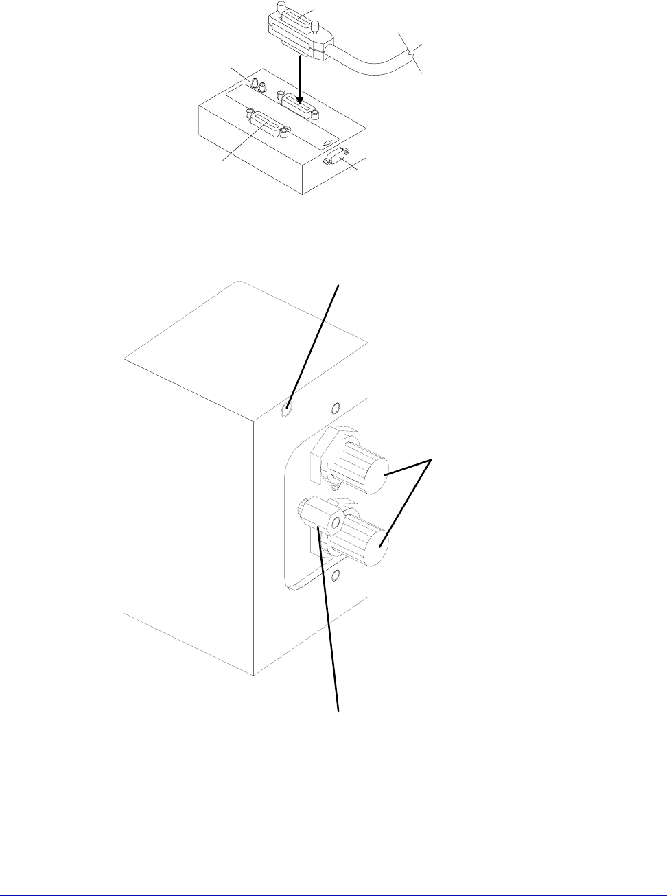
computer and the controller.
Fig. 39. GPIB switch box.
To probe station connector
To probe-station computer
GPIB card connector
(VNA Cal or Aux IN, depending on model)
To remote host
T
o pro
b
e-s
t
a
ti
on con
t
ro
ll
e
d
i
ns
t
rumen
t
s
Indicator LEDs
Green for power on
Red for host disconnected
Store standoff here if not needed
Install standoff here if you are using
a Dual Triax cable (HD4156), or a Quadrax
cable with an HP4142 or HP4145
Triax Connectors for
Guarded Chuck
Fig. 40. Dual Triax or Quadrax Cable Standoff Position:11500, 11700, 11800, 12500, 12700, and
12800 Only.