晶圆测试说明书Cascade-11861-6-Manual.pdf - 第72页
48 • Summit 11K/12K Probe Station User’ s Guide 4. Slide the slotted seals into the TopHat ring and push over the positioner extender arm. 5. Install the TopHat cover and se al the cover with the objective. 6. Push down …
Chapter 3: Installing •
47
9. Check the positioner for clearance. The probe mount rests approximately 8
mm to 13 mm (0.3 inch to 0.5 in.) above the chuck top.
10.Mount the probes and probe cables.
11.Planarize the probe head. See ACP probe documentation.
INSTALLING THE PROBE CARD HOLDER
See the instructions that are included with the probe card holder.
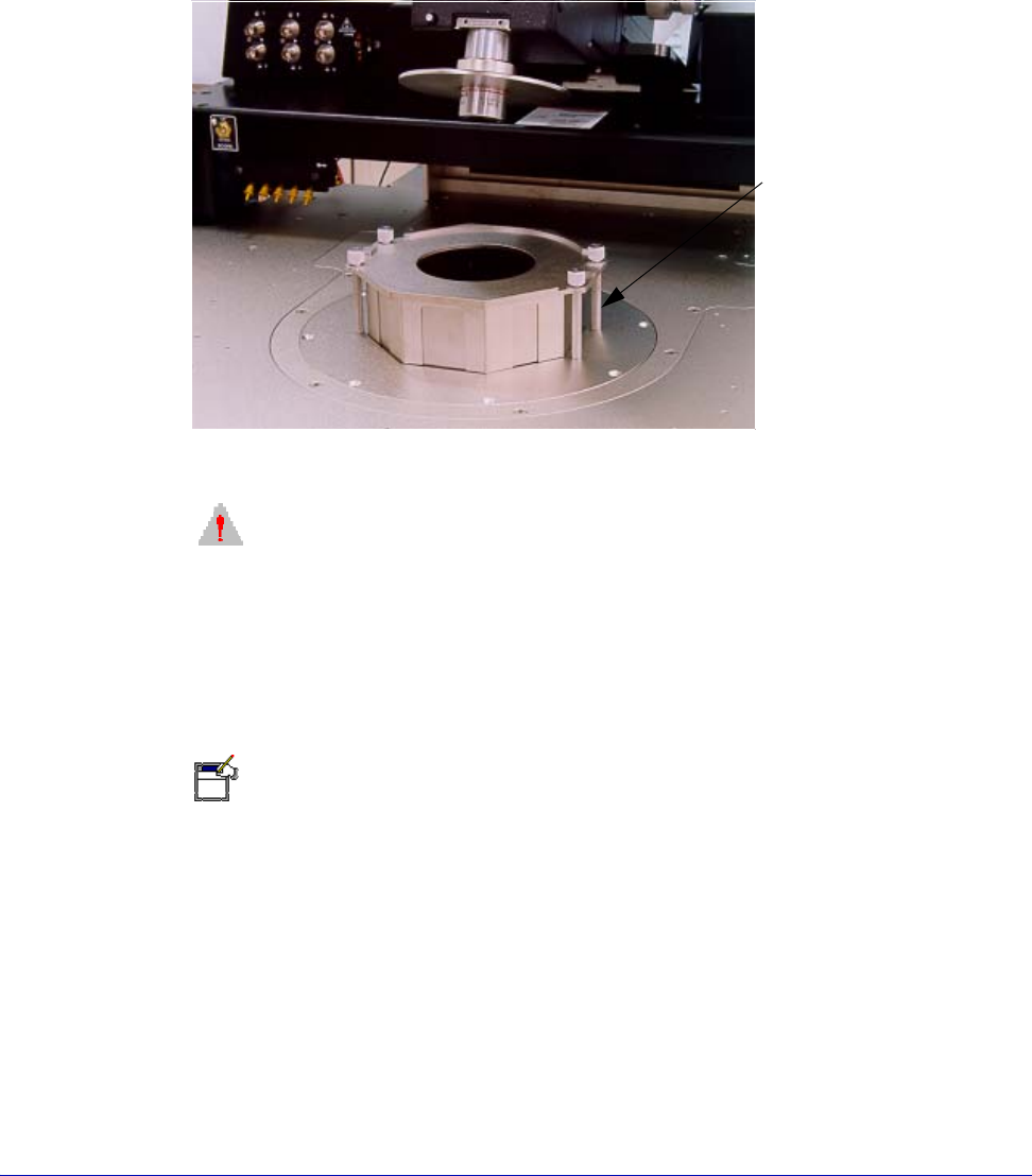
INSTALLING THE TOPHAT
(MicroChambered Stations Only)
To install the MicroChamber TopHat
1. Remove the blank seals from the positioner entry areas.
2. Screw in the four standoffs on the platen. See figure 36 on p. 48.
3. Insert the TopHat ring on top of the platen.
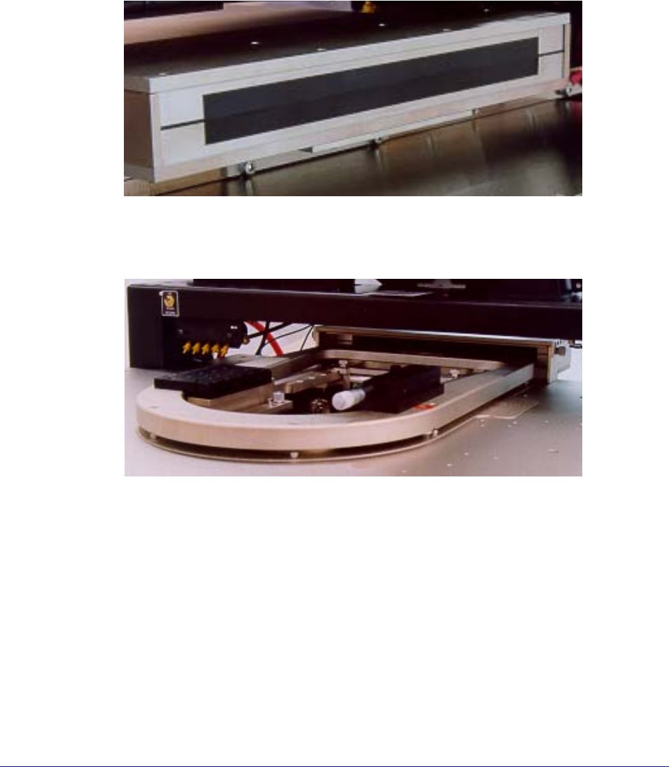
Fig. 34. Exit box (rear view).
Fig. 35. Probe card holder.
48
• Summit 11K/12K Probe Station User’s Guide
4. Slide the slotted seals into the TopHat ring and push over the positioner
extender arm.
5. Install the TopHat cover and seal the cover with the objective.
6. Push down the screws to catch the standoffs and finger-tighten.
CAUTION
TILT-BACK BRIDGE
Center the programmable scope transport before raising or lowering the tilt-back
bridge or damage can occur to the probe station and/or accessories. Scope travel
is limited to 1-inch in the x-, y-axes when using the TopHat.
7.Nucleus software supports the programmable scope transport if the optional
autoprobe module (PN 123-567) is purchased. This module controls the ECX-56
Box accessories.
N
OTE
The DC configuration of the TopHat is similar to the preceding graphic. However,
steel/rubber seals slide to allow positioning of the probe arms. This seal provides a
“light tight” environment for the wafer. Note that the TopHat is inverted to allow the
removal of positioners when the lid is removed. A comparable TopHat is shown
below.
INSTALL CHUCK BIAS AND DOOR INTERLOCK
Electrical isolation and chuck biasing
(11500, 11700, 11800, 12500, 12700 and 12800 only)
Fig. 36. TopHat for RF.
Standoffs (4)
Chapter 3: Installing •
49
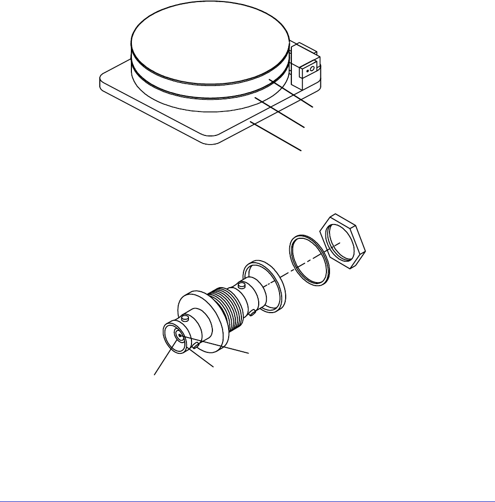
The chuck is composed of three layers: shield, guard, and surface (fig. 37). This
structure electrically isolates the surface from the rest of the station, enabling you
to use guarded measurement techniques for accurate and rapid current
measurements. Two triax connectors enable you to apply a bias voltage to the
chuck's surface and a guard voltage to the chuck's guard layer.
The chuck-bias triax connectors are located on the back of the station (fig. 38).
• The outer shield of the triax connector makes an electrical connection with the
MicroChamber and the shield layer of the chuck.
• The middle shield of the connector makes a connection to the guard layer of
the chuck (FemtoGuard or AttoGuard)
• The center connector makes a connection with the chuck surface
.
Fig. 37. Chuck layers.
Surface layer
Guard layer
Shield layer
Fig. 38. Chuck triaxial connectors.
Chuck surface
connection
MicroChamber
connection
Chuck guard-layer
connection