晶圆测试说明书Cascade-11861-6-Manual.pdf - 第45页
Chapter 2: Station Specifications • 21 11500 G UARDED P ROB E S TATIONS The 11500 probe stations ha ve a triaxial guarded architecture. Th e station provides a low-residua l-capacitance me asurement environment (includin…
20
• Summit 11K/12K Probe Station User’s Guide
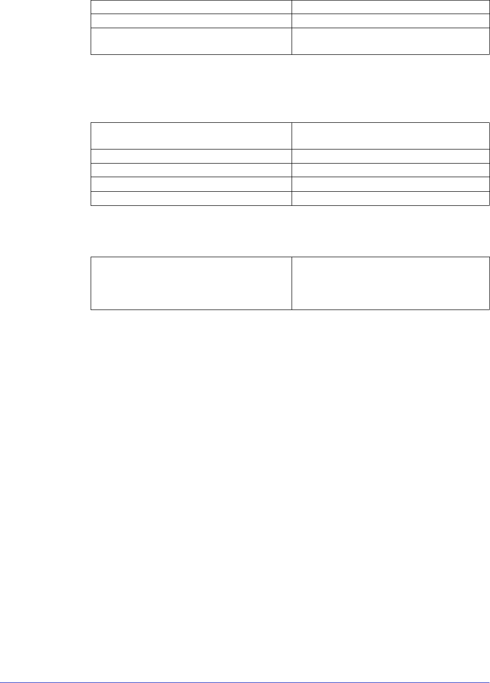
The 11100 probe stations are designed so that can be easily reconfigured and
upgraded. The following sections describe specifications and requirements.
Chuck Specifications
Total System Planarity
Planarity includes error from wafer chuck, theta rotations, and travel flatness.
Light tight Yes
Enclosure Dry air, inert gas purge capable
Maximum number of positioners Eight DCM (seven with high-power
microscope) or four RF
Flatness 0.39 mils (10 microns) across total
surface
Isolation, chuck to shield > 10 TΩ
Auxiliary chucks Two with individual vacuum controls
Breakdown bias voltage > 1000-volts
Vacuum distribution area 13, 75, or 152 mm (selectable)
Total system planarity <20-micron (0.8 mil) across 101 mm
(4 in.) circle
<30-micron (1.2 mil) across 203 mm
(8 in.) circle
Chapter 2: Station Specifications •
21
11500 GUARDED PROBE STATIONS
The 11500 probe stations have a triaxial guarded architecture. The station
provides a low-residual-capacitance measurement environment (including the
chuck) for substrate measurements. By eliminating residual capacitance, the
11500 enables you to make precise, low-level measurements using shorter
integration intervals. Typical improvements are from 100 to 1000 times in the sub-
pA range in measurement speed.
The MicroChamber works as a Faraday cage to further reduce chuck variation to
30 fF (11550), and as low as 3fF (11560) with the AttoGuard version. This feature
enables you to measure capacitance without having to null position-dependent
capacitance changes.
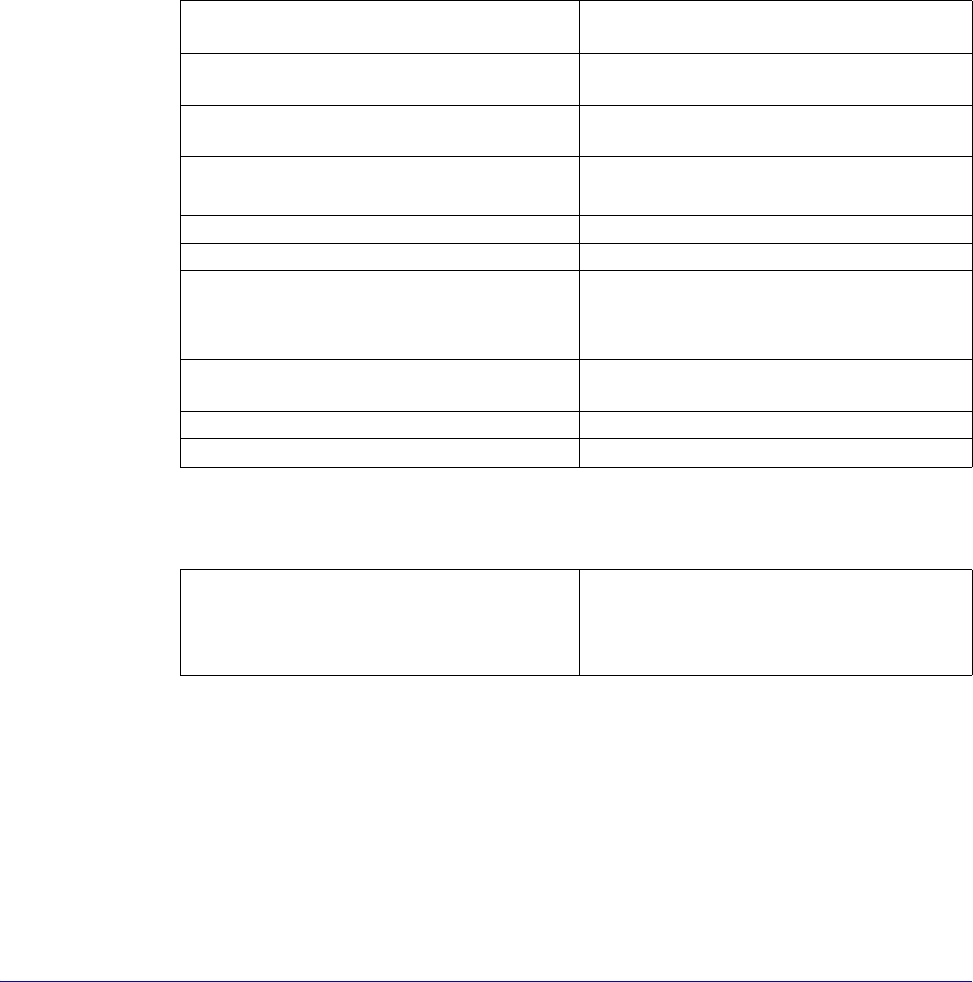
Chuck Specifications
Total System Planarity
Planarity includes error from wafer chuck, theta rotations, and travel flatness.
Flatness 10-micron (0.39 mil) across total
surface
Residual capacitance, chuck to shield
(FemtoGuard version)
< 20 pF
Residual capacitance, chuck to shield
(AttoGuard version)
< 0.2 pF
Capacitance variation over chuck
surface
≤ 3 fF with AttoGuard
≤ 30 fF with FemtoGuard
Isolation, chuck to shield > 10 TΩ
Breakdown bias voltage > 1000-volts
Chuck leakage current after 10
seconds (FemtoGuard version)
5 fA @ 0-volts
10 fA @ 10-volts
20 fA @ 100-volts
Chuck leakage current after 10
seconds (AttoGuard version)
3 fA @ 0 to 100-volts
Vacuum distribution area 13, 75, or 152 mm (selectable)
Auxiliary chucks Two with individual vacuum control
Total system planarity <20-micron (0.8 mil) across 101 mm
(4 in.) circle
<30-micron (1.2 mil) across 203 mm
(8 in.) circle
22
• Summit 11K/12K Probe Station User’s Guide
11600 THERMAL PROBE STATIONS
The 11600 provides temperature control of wafers over a -65
o
C to +200
o
C range
(300
o
C on HT version). Since the wafer is enclosed in the low-volume
MicroChamber, temperature transitions are fast. You can verify the calibration at
each temperature level using a Cascade ISS on an integrated auxiliary stage and
Cascade's VNA calibration software.
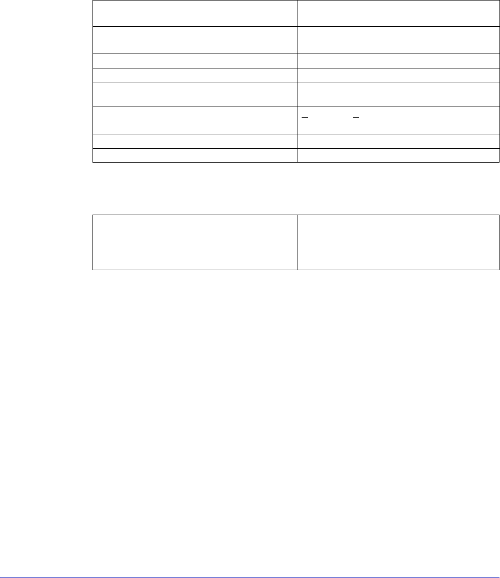
Chuck Specifications
Total System Planarity
Planarity includes all error sources.
Flatness 2-micron (1 mil) to 130 °C, 51-micron
(2 mil) to 200 °C
Residual capacitance, chuck to shield
(standard version)
< 950 pF
Isolation, chuck to shield > 1 GΩ at 500-volts DC at 25 °C
Breakdown bias voltage > 500-volts
Temperature range
-65 °C to 200 °C maximum (controller
dependent). 300
o
C on HT version.
Temperature uniformity +0.5° C or +0.5%,
whichever is higher
Vacuum distribution area 13, 75, or 152 mm (selectable)
Auxiliary chucks Two with individual vacuum controls
Total system planarity <30-micron (1.2 mil) across 101 mm
(4 in.) circle
<40-micron (1.6 mil) across 203 mm
(8 in.) circle