00198442-04_UM_TX-V2_EN.pdf - 第128页
3 Technical data and assemblie s Instruction manual SIPLACE TX 3.5 Placement head From software version 714.0 12/2020 128 3 Fig. 3.5 - 7 SIPLACE MultiS tar - back view , function groups part 3 (1) Component sensor (2) As…
Instruction manual SIPLACE TX 3 Technical data and assemblies
From software version 714.0 12/2020 3.5 Placement head
127
3
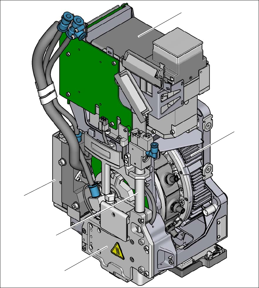
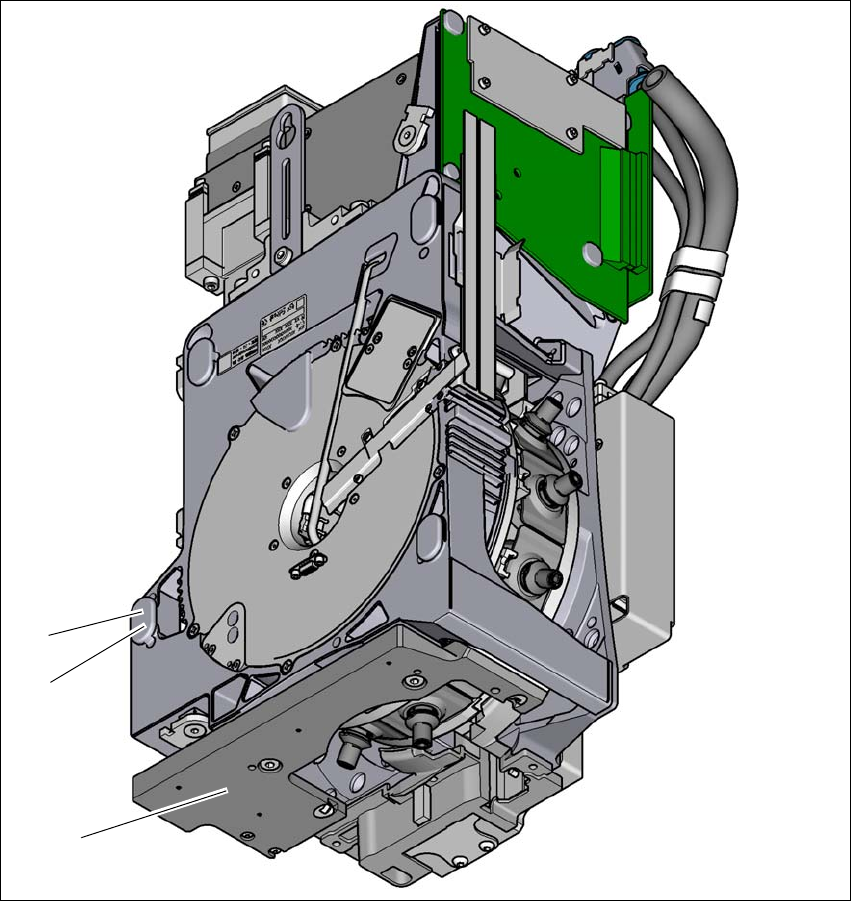
Fig. 3.5 - 6 SIPLACE MultiStar - front view, function groups part 2
(1) Component camera C&P, type 30, 27 x 27, digital
(2) Torque motor for star drive
(3) Z drive (linear motor)
(4) Return cylinder
(5) Pressure control valve
(1)
(2)
(3)
(4)
(5)
3 Technical data and assemblies Instruction manual SIPLACE TX
3.5 Placement head From software version 714.0 12/2020
128
3
Fig. 3.5 - 7 SIPLACE MultiStar - back view, function groups part 3
(1) Component sensor
(2) Assembly position for component height of up to 11.5 mm
(3) Assembly position for component height of up to 6 mm
(3)
(2)
(1)

Instruction manual SIPLACE TX 3 Technical data and assemblies
From software version 714.0 12/2020 3.5 Placement head
129
3.5.5.1 Assembly positions of SIPLACE MultiStar CPP
The SIPLACE MultiStar CPP head can be fitted to the head mount in two different positions:
– SIPLACE MultiStar CPP in the top assembly position
In this position, all components can be processed up to a size of 50 mm x 40 mm and a height
of 15.5 mm. 3
– SIPLACE MultiStar CPP in the bottom assembly position
In this position, the CPP head places components up to a size of
27 mm x 27 mm and a component height of 6 mm for the SIPLACE TX1/TX2 and 4 mm for
the SIPLACE TX2i, using the Collect&Place method. 3
Observe the following rules when defining the assembly position:
The head height must be the same for all heads in the same placement area.
– Install the SIPLACE MultiStar CPP in the bottom assembly position
Always in the top assembly position, if combined with the following assemblies:
– Stationary component camera
– TwinStar
3.5.5.2 Classification of component range to be processed
3
Component
class
Component
size
Assembly
position
*a
of CPP
head
Component
height
Component
camera type
Small compo-
nent
K_BE
01005 to 15 mm
x 15 mm
Top Up to 8.5 mm
Head camera,
type 45
Bottom Up to 6.0 mm
Small compo-
nent
K_BE
01005 to 27 mm
x 27 mm
Top Up to 8.5 mm
Head camera,
type 30
Bottom Up to 6.0 mm
Medium sized
component, type
M_BE_1
< 27 x 27 mm
Top
Between 8.5 and
11.5 mm
Stationary compo-
nent camera,
type 33
Bottom Not possible
Medium sized
component, type
M_BE_2
Between
27 mm x 27 mm
and
32 mm x 32 mm
Top 11.5 mm
Bottom Not possible
Large compo-
nent
G_BE
Between
32 mm x 32 mm
and
50 mm x 40 mm
Top Up to 15.5 mm
Stationary compo-
nent camera,
type 33
Bottom Not possible
Tab. 3.5 - 1Classification of component range to be processed
*)a Please observe the rules for assembly position heights in section 3.5.5.1
, page 129.