00198442-04_UM_TX-V2_EN.pdf - 第153页
Instruction manual SIPLACE TX 3 Technical data and assemblies From software version 714.0 12/2020 3.8 SIPLACE tape feeder modul es for SIPLACE TX 153 3.8 SIPLACE t ape feeder modules for SIPLACE TX The SIPLACE TX uses th…

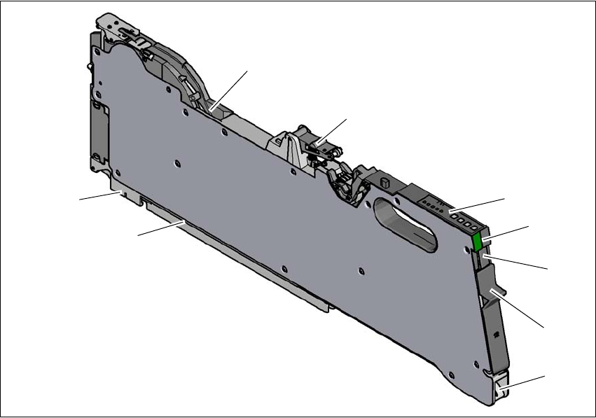
3 Technical data and assemblies Instruction manual SIPLACE TX
3.7 PCB conveyor system From software version 714.0 12/2020
152
3.7.6.4 Ink spot criteria
3
Methods - Synthetic fiducial recognition method
- Mean grayscale value
- Histogram method
- Template matching
Shapes and sizes of fiducials/
structures for
Synthetic fiducials
Other methods
For dimensions of synthetic fiducials, see section 3.7.6.3
Fidu-
cial criteria, page 151.
Min. 0.3 mm
Max. 5 mm
Masking material Good coverage
Recognition time Depends on the method: 20 ms - 0.2s

Instruction manual SIPLACE TX 3 Technical data and assemblies
From software version 714.0 12/2020 3.8 SIPLACE tape feeder modules for SIPLACE TX
153
3.8 SIPLACE tape feeder modules for SIPLACE TX
The SIPLACE TX uses the SIPLACE SmartFeeder X and the SIPLACE SmartFeeder Xi. The
specified SIPLACE tape feeder modules are compatible with the SIPLACE TX changeover tables.
Key features of the SIPLACE tape feeder modules include high pickup position precision, online
programming and simple handling of feeder module changeovers during the placement process.
The power supply to the feeder modules is contactless and uses an inductive interface. Each
feeder module communicates with the feeder module control unit (FCU) via two optoelectronic
channels (optical fiber). The two interfaces form the EDIF assembly (energy and data interface).
3.8.1 SIPLACE tape feeder module
3.8.1.1 Tape material
The tape width spectrum for SIPLACE TX ranges from 4 mm to 56 mm. The tape material is blister
or paper. Component tapes with a permanently adhesive cover foil (PSA foil) can also be pro-
cessed as a default. The design of the tape feeder modules was based on the following tape stan-
dards:
DIN EN 60286-3 (12/1998) / IEC 60286-3 (12/1997)
JIS C 0806-3 (1999)
ANSI/EIA 481-C (10/2003)
IEC 60286-3-2 3
3.8.1.2 Manual removal of tantalum capacitors which were not picked up
To prevent tantalum capacitors which were not picked up from causing the tape material to burn
when it is cut, the user interface has been extended to include the option "Stop immediately on
pickup error". This option must be enabled in SIPLACE Pro. On the placement machine, the com-
ponent that was not picked up is stepped forward again until it is ready for removal from the com-
ponent tape. The track is deactivated and the operator is sent an error message to remind him to
pick up the tantalum component from the tape. If an alternative track is available, the placement
machine continues placing. The operator is able to stop the placement machine, however, and re-
move the tantalum component. If no alternative track is available and it is not possible to continue
placement with other components, the placement machine will stop. At this point, the operator can
again remove the tantalum component and acknowledge the error. Once the operator has re-
started the placement machine, placement is continued and components are picked up from the
track that is now enabled once more.
3
PLEASE NOTE
This software function is also a good idea for expensive components.
Please observe the safety instructions for capacitors on metallic powder basis (see section 2.4.3,
page 74
).
3 Technical data and assemblies Instruction manual SIPLACE TX
3.8 SIPLACE tape feeder modules for SIPLACE TX From software version 714.0 12/2020
154
3.8.1.3 Design of the SIPLACE SmartFeeder X
The following diagram shows the design of the SIPLACE SmartFeeder X.
3
Fig. 3.8 - 1
SIPLACE SmartFeeder X
(1) Entry to the tape guide channel with tape spring
(2) Flap on cover foil container
(3) Removal handle, engaged
(4) Status display
(5) Operating panel - LED display
(6) Foil rocker
(7) Tape guide channel outlet
(8) Front slider guide
(9) Back slider guide
(1)
(2)
(3)
(4)
(5)
(6)
(8)
(9)
(7)