00198442-04_UM_TX-V2_EN.pdf - 第83页
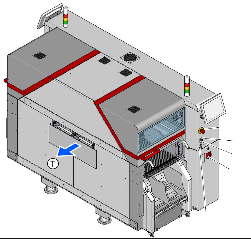
Instruction manual SIPLACE TX 2 Operational safety From software version 714.0 12/2020 2.5 Safety features 83 2 Fig. 2.5 - 3 Position of switches and buttons - PCB input end (location 1) (1) EMERGENCY S TOP button (2) S …
2 Operational safety Instruction manual SIPLACE TX
2.5 Safety features From software version 714.0 12/2020
82
2.5.2 Switches and buttons
2.5.2.1 Positions of switches and buttons
2
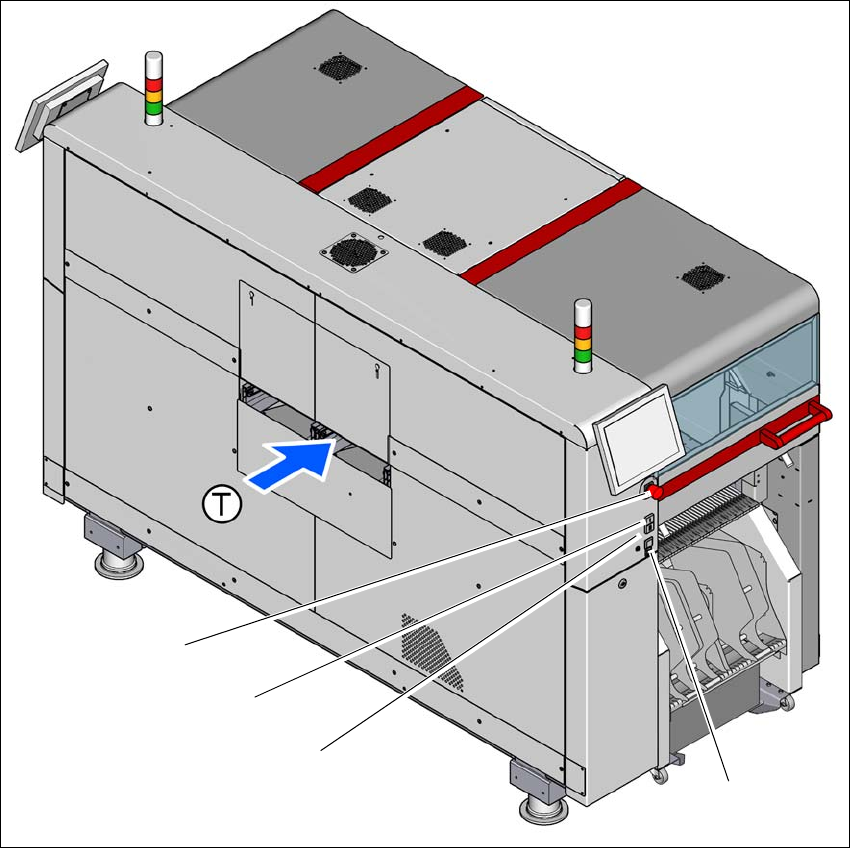
Fig. 2.5 - 2 Position of switches and buttons - PCB output end (location 2)
(1) EMERGENCY STOP button
(2) Start button (white)
(3) Stop button (black)
(4) Main switch
(5) Button for docking and undocking the component trolley at the respective location
(T) PCB transport direction
(3)
(1)
(4)
(2)
(5)
Instruction manual SIPLACE TX 2 Operational safety
From software version 714.0 12/2020 2.5 Safety features
83
2
Fig. 2.5 - 3 Position of switches and buttons - PCB input end (location 1)
(1) EMERGENCY STOP button
(2) Start button (white)
(3) Stop button (black)
(4) Button for docking and undocking the component trolley at the respective location
(T) PCB transport direction
(3)
(1)
(4)
(2)
2 Operational safety Instruction manual SIPLACE TX
2.5 Safety features From software version 714.0 12/2020
84
2.5.2.2 Position of the position switches on the placement machine
2
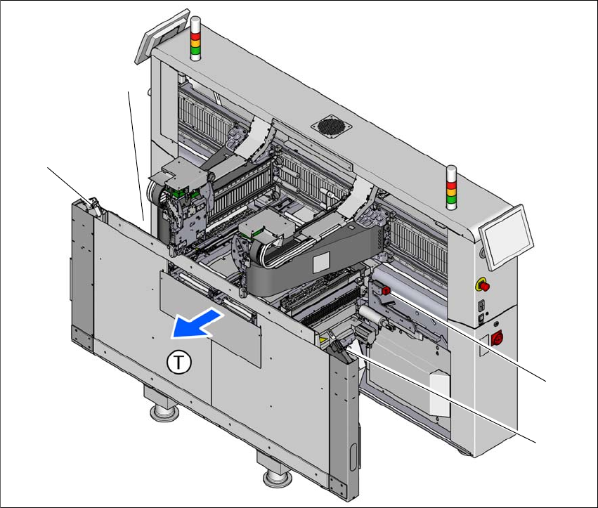
Fig. 2.5 - 4 Position of the position switches
(1) Position switches, location 1
(2) Protective switch for COT insert, location 1
(3) Protective switch for COT insert, location 2
(4) Position switches, location 2
The protective covers are mechanically locked during placement machine operation. The protec-
tive covers can only be opened once the stop button has been pressed.
(4)
(1)
(3)
(2)