00198442-04_UM_TX-V2_EN.pdf - 第209页
Instruction manual SIPLACE TX 4 Setting up and commissioning From software version 714.0 12/2020 4.5 Setting up the placement machine 209 4.5.7.4 Fitting the floor bra ce (optional) Item no. 00588122- xx Fl oor brace set…
4 Setting up and commissioning Instruction manual SIPLACE TX
4.5 Setting up the placement machine From software version 714.0 12/2020
208
4
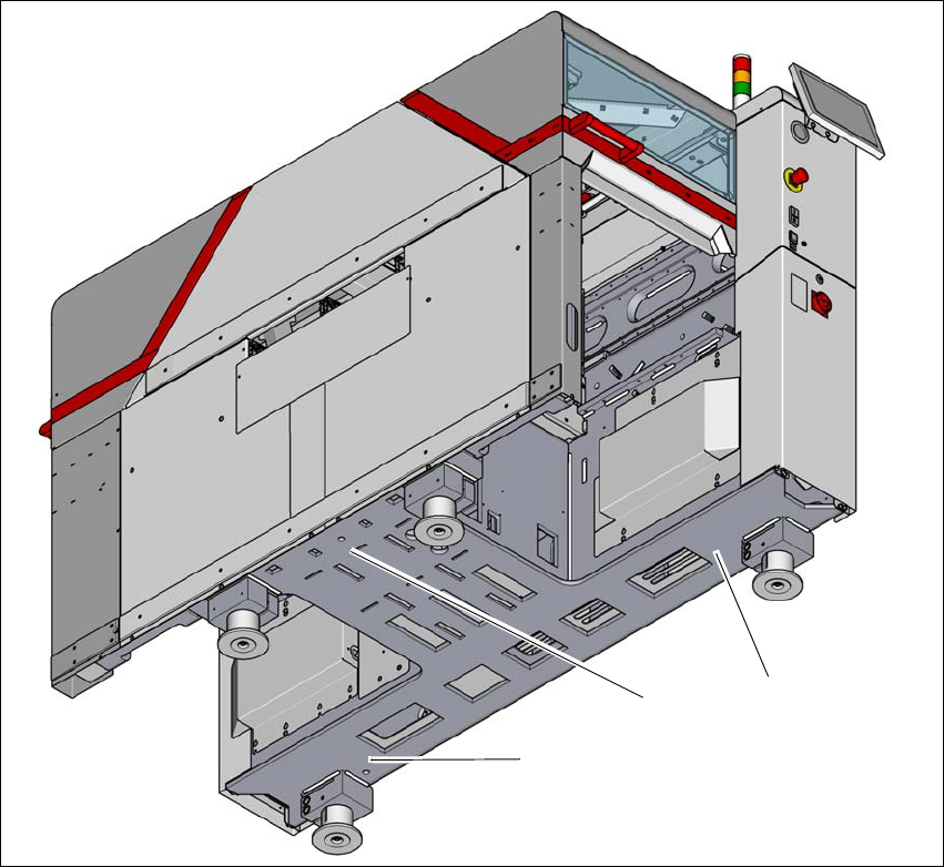
Fig. 4.5 - 7 Contact positions for the air cushion transport system
(1) Three contact points for the air cushion transport system
(1)
(1)
(1)
Instruction manual SIPLACE TX 4 Setting up and commissioning
From software version 714.0 12/2020 4.5 Setting up the placement machine
209
4.5.7.4 Fitting the floor brace (optional)
Item no. 00588122-xx Floor brace set for TX
The placement machine can be secured against sliding in the event of strong vibrations (e.g.
earthquakes) with a floor brace, if required.
Fit a floor brace to each placement machine foot.
4
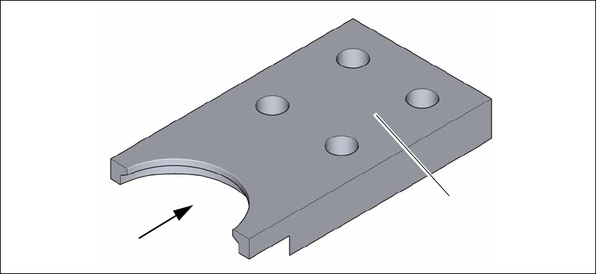
Fig. 4.5 - 8 Floor brace
Place the floor brace (1) over the placement machine foot.
Attach the floor brace to the ground with suitable fixtures, at the four holes (2) provided.
(1)
(2)
4 Setting up and commissioning Instruction manual SIPLACE TX
4.5 Setting up the placement machine From software version 714.0 12/2020
210
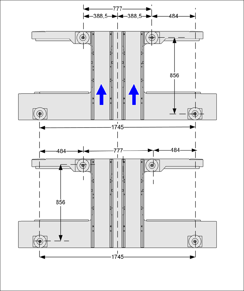
4.5.8 Placement machine foot clearances and the stationary PCB conveyor edges
4.5.8.1 Placement machine foot clearances
4
Fig. 4.5 - 9 Placement machine foot clearances in millimeters