00198442-04_UM_TX-V2_EN.pdf - 第210页
4 Setting up and commissioning In struction manual SIPLACE TX 4.5 Setting up the placement mac hine From software version 714.0 12/2020 210 4.5.8 Placement machine foot clea rances an d the stationary PCB c onveyor edges…
Instruction manual SIPLACE TX 4 Setting up and commissioning
From software version 714.0 12/2020 4.5 Setting up the placement machine
209
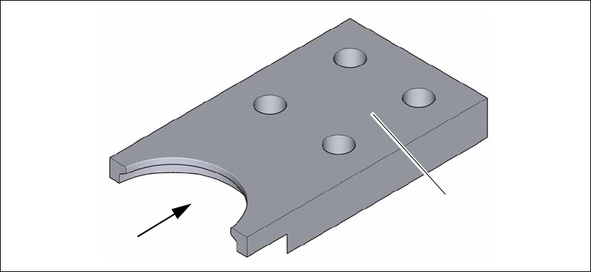
4.5.7.4 Fitting the floor brace (optional)
Item no. 00588122-xx Floor brace set for TX
The placement machine can be secured against sliding in the event of strong vibrations (e.g.
earthquakes) with a floor brace, if required.
Fit a floor brace to each placement machine foot.
4
Fig. 4.5 - 8 Floor brace
Place the floor brace (1) over the placement machine foot.
Attach the floor brace to the ground with suitable fixtures, at the four holes (2) provided.
(1)
(2)
4 Setting up and commissioning Instruction manual SIPLACE TX
4.5 Setting up the placement machine From software version 714.0 12/2020
210
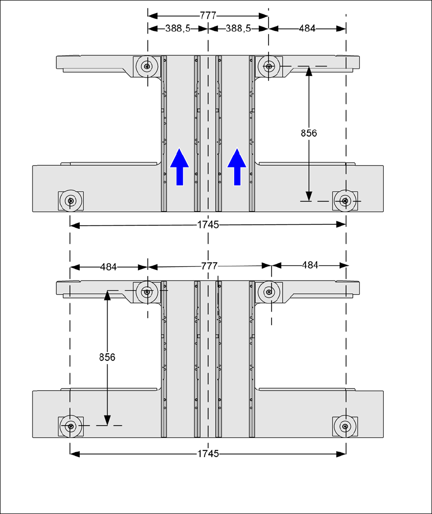
4.5.8 Placement machine foot clearances and the stationary PCB conveyor edges
4.5.8.1 Placement machine foot clearances
4
Fig. 4.5 - 9 Placement machine foot clearances in millimeters
Instruction manual SIPLACE TX 4 Setting up and commissioning
From software version 714.0 12/2020 4.6 Adjusting the component trolley to the PCB conveyor height
211
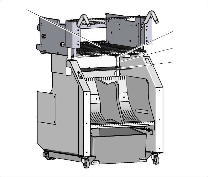
4.6 Adjusting the component trolley to the PCB conveyor
height
The component trolley can be easily and quickly adjusted to the following PCB conveyor heights:
900 mm 4
930 mm (standard height) 4
950 mm 4
4
Fig. 4.6 - 1 Component trolley
(1) Holes for the transport heights of 900, 930 and 950 mm.
(2) Changeover table
900 mm
930 mm
950 mm
(1)
(2)