00198442-04_UM_TX-V2_EN.pdf - 第300页
6 Station extensions Instruction manual SIPLACE TX 6.9 Smart Pin Support From software version 714.0 12/2020 300 6.9 Smart Pin Support Item no. 031650 96-01 Gripper unit gantr y 1 Item no. 031643 67-01 Gripper unit gantr…
Instruction manual SIPLACE TX 6 Station extensions
From software version 714.0 12/2020 6.8 Support pin
299
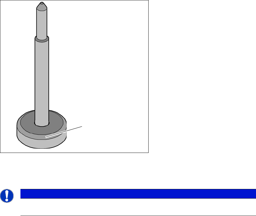
6.8 Support pin
Item no. 00119680-01 Support pin
Wide boards tend to deflect during placement such that, under certain circumstances, the compo-
nents can no longer be placed with the desired accuracy. Highly curved PCBs also affect the
placement accuracy. This problem can be easily rectified by fitting support pins on the lifting table.
6
Fig. 6.8 - 1 Support pin
(1) Magnetic base
6
PLEASE NOTE
Make sure that the magnetic base of the Support Pin is not placed under the side wall of
the conveyor. This could lead to the side wall profile being damaged.
(1)
6 Station extensions Instruction manual SIPLACE TX
6.9 Smart Pin Support From software version 714.0 12/2020
300
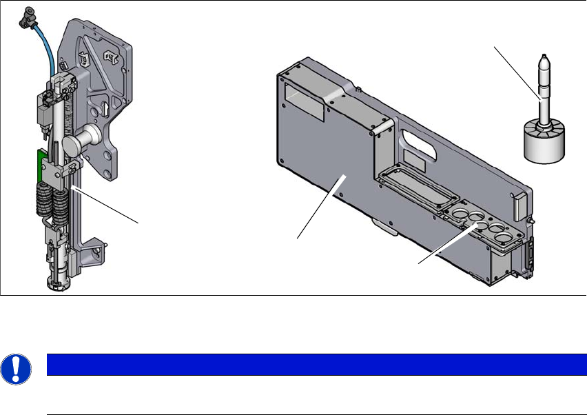
6.9 Smart Pin Support
Item no. 03165096-01 Gripper unit gantry 1
Item no. 03164367-01 Gripper unit gantry 2
Item no. 00588322-01 Smart pin magazine
Item no. 03089582-01 Support pin
The Smart Pin Support option automatically places support pins on the lifting table. A gripper unit
is used to take the support pins out of the smart pin magazine and place them in the predefined
positions. Before placing the smart support pin, the placement area is cleaned of any impurities
with a gentle blast of air. In addition, the correct position of the support pin is checked after place-
ment with the PCB camera.
Smart pin magazine
There is a smart pin magazine T5 with 5 garages for automatic changing of max. 5 support pins.
The smart pin magazine T5 is fitted to the component trolley in location 1. The gripper unit fitted
to the side, next to the head, restricts the travel range of the head. The area of the changeover
tables which can not be reached is used optimally by the T5 pin magazine. When using smart pin
support, there are 68 x 8 mm tracks available.
6
Fig. 6.9 - 1 Smart Pin Support
6
PLEASE NOTE
For details about the Smart Pin Support option, please refer to the "Smart Pin Support
User Guide", German+English [item no. 00198632-xx].
Support pin
Gripper unit
Garages
Smart pin magazine

Instruction manual SIPLACE TX 7 Maintenance
From software version 714.0 12/2020
301
7 Maintenance
To ensure that your SIPLACE placement machine always runs properly during production, we ad-
vise that you service the placement machine on a regular basis.
The SIPLACE TX maintenance documentation contains recommendations for the maintenance
tasks to be performed at each maintenance interval. Workflows have been defined for each main-
tenance interval. These combine the individual steps to form an efficient sequences of tasks in
order to optimize the "Uptime" for each maintenance task.
7
Maintenance workflows
We differentiate between four workflows which are to be performed independently of one another
per maintenance interval.
– Workflow 1: Weekly maintenance tasks.
– Workflow 2: Combination of weekly and 3-monthly maintenance tasks.
– Workflow 3: Combination of weekly and 6-monthly maintenance tasks.
– Workflow 4: Combination of weekly and 12-monthly maintenance tasks.
Planning workflows
Each workflow is supported with a document (job card), which guides you efficiently through the
maintenance work.
Example for the frequency of individual workflows over a period of one year:
– Workflow 1: 45 times / year
– Workflow 2: 4 times / year
– Workflow 3: 2 times / year
– Workflow 4: 1 time / year
PLEASE NOTE
Job cards for maintenance
All maintenance work is explained in detail in the corresponding job cards and clearly il-
lustrated in the diagrams.