00198442-04_UM_TX-V2_EN.pdf - 第265页
Instruction manual SIPLACE TX 5 Tasks at the placement machine From software version 714.0 12/2020 5.14 Docking the component tr olley in or out 265 5.14 Docking the component trolley in or out 5.14.1 Safety instructions…
5 Tasks at the placement machine Instruction manual SIPLACE TX
5.13 Avoiding track errors From software version 714.0 12/2020
264
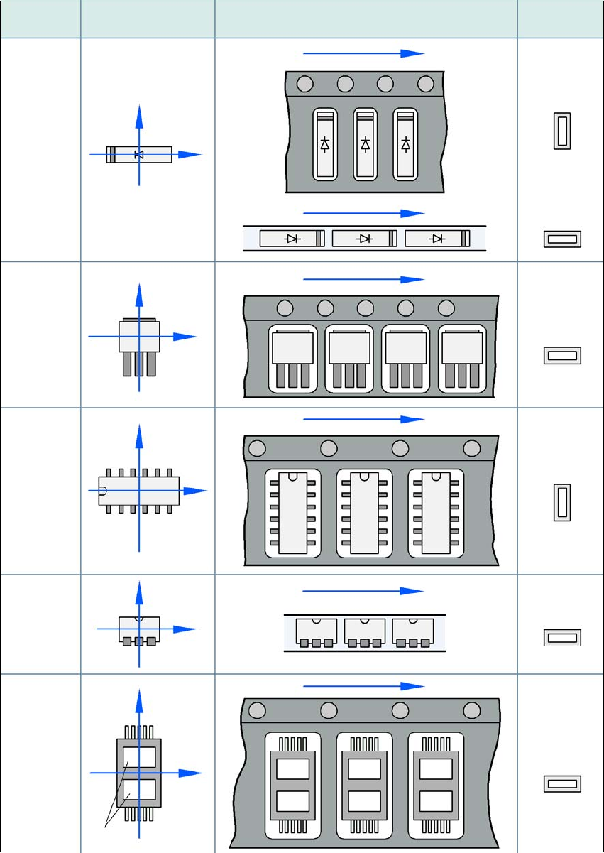
5.13.2 Component coordinate system and pickup angle
5
Fig. 5.13 - 1 Position of the component and its pick-up angle
Special
component
Stick
magazine:
Chip-
components
with polarity
0402
2220
The anode must be
aligned with the +X
coordinate.
Package form
type
0° coordinate system
Position in the feeder module
Pickup angle/
nozzle angle
Tape:
SOT 23
Stick
magazine:
Tape:
Tape:
SO-IC
DIL-IC
SOT 194
Tape:
Holes
Y
X
Y
X
Y
X
Y
X
Y
X
90°
90°
0°
90°
-90°
0°
Instruction manual SIPLACE TX 5 Tasks at the placement machine
From software version 714.0 12/2020 5.14 Docking the component trolley in or out
265
5.14 Docking the component trolley in or out
5.14.1 Safety instructions for docking component trolleys in and out
Also follow the safety instructions given in section 2.4.10, page 79.
5
5
There is a button at each location (1 and 2). The safety concept for the component trolley change-
over specifies that the operator should push this button at the relevant placement machine loca-
tion, to dock or undock the component trolley.
WARNING
DANGER OF CRUSHING!
Risk of crushing when docking and undocking the component trolley.
Always dock/undock the component trolley alone.
When docking and undocking, make sure that there are no body limbs in the travel
area of the component trolley.
PLEASE NOTE
Docking only possible if protective cover is closed
Close the protective covers.
5 Tasks at the placement machine Instruction manual SIPLACE TX
5.14 Docking the component trolley in or out From software version 714.0 12/2020
266
5
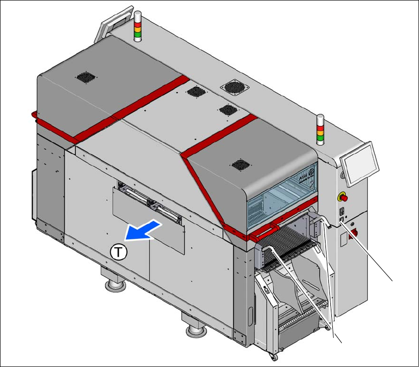
Fig. 5.14 - 1 Safety instructions for docking and undocking the component trolley (example of location 2)
(1) Button for docking and undocking the component trolley at location 2
(2) Handles
(T) Direction of PCB transport
(1)
(2)