00198442-04_UM_TX-V2_EN.pdf - 第259页
Instruction manual SIPLACE TX 5 Tasks at the placement machine From software version 714.0 12/2020 5.11 Observing displays on th e feeder module 259 5.1 1 Observing displays on the feeder module 5 Fig. 5.1 1 - 1 SIPLACE …

5 Tasks at the placement machine Instruction manual SIPLACE TX
5.10 Setting up the feeder modules From software version 714.0 12/2020
258
5.10.4.4 Splice sensors
Splice sensors can be retrofitted to the SIPLACE SmartFeeder.
SIPLACE SmartFeeders with a splice sensor already installed can also be supplied (see section
3.8
, from page 153).
5.10.5 Configuring components on the SIPLACE SmartFeeder
The operation and setting up is described in the SIPLACE SmartFeeder X /Xi job guides.
Instruction manual SIPLACE TX 5 Tasks at the placement machine
From software version 714.0 12/2020 5.11 Observing displays on the feeder module
259
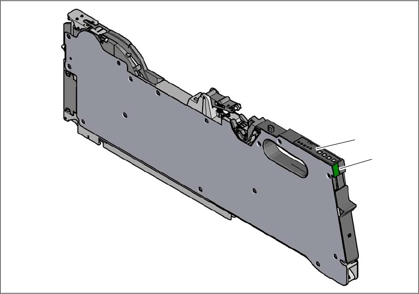
5.11 Observing displays on the feeder module
5
Fig. 5.11 - 1 SIPLACE SmartFeeder X
(1) Operating panel - LED display
(2) Status display
(2)
(1)
5 Tasks at the placement machine Instruction manual SIPLACE TX
5.11 Observing displays on the feeder module From software version 714.0 12/2020
260
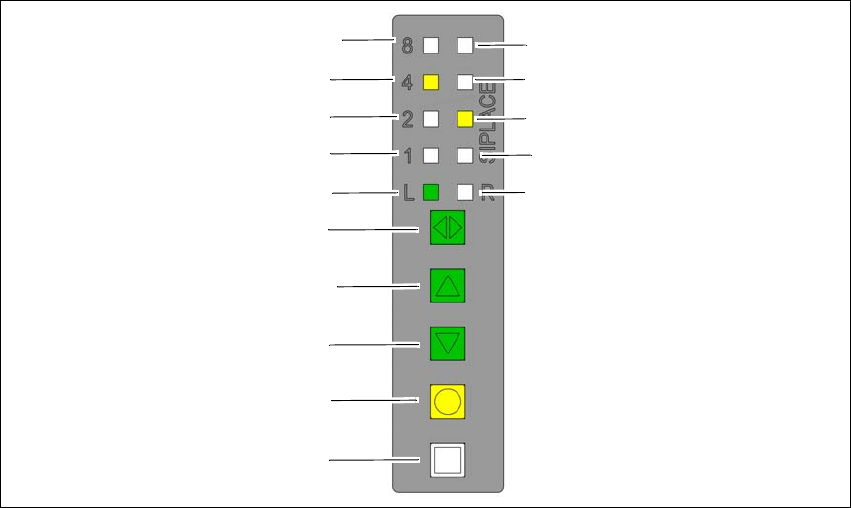
5.11.1 Operating panel - LED display
The SIPLACE SmartFeeder have a multicolored status display for each track and LED displays,
to indicate the operating states.
5
Fig. 5.11 - 2 Buttons, LED and status displays: Example of SIPLACE SmartFeeder 2x8 mm
(1) SET button
(2) FOIL button
(3) BACK button
(4) FORWARD button
(5) Track change button for switching between right and left
(6) LED L left track active
(7) LED 1 mm increment for left track
(8) LED 2 mm increment for left track
(9) LED 4 mm increment for left track
(10) LED 8 mm increment for left track
(11) LED R right track active
(12) LED 1 mm increment for right track
(13) LED 2 mm increment for right track
(14) LED 4 mm increment for right track
(15) LED 8 mm increment for right track
(8)
(1)
(2)
(3)
(4)
(5)
(6)
(7)
(9)
(10)
(15)
(14)
(13)
(12)
(11)